We developed a custom solution for model OCD-PPA1G-0812-B150-CRW. Selected when multi-turn absolute feedback is required through a parallel push-pull interface, using a 58 mm blind hollow structure with 15 mm shaft, without moving to a fieldbus architecture. Typical production lead time: 15 working days. The referenced configuration combines 12-bit single-turn resolution, 8-bit multi-turn resolution, Gray code, and a mechanical gear train without battery.
Key Specifications
- Interface: parallel push-pull
- Resolution: 12-bit single-turn + 8-bit multi-turn
- Code: Gray
- Multi-turn: mechanical gear train, no battery
- Supply: 10–30 VDC
- Protection: IP65 shaft side, IP65 housing
- Structure: 58 mm blind hollow, 15 mm shaft, 30 mm depth
- Cable: 1 m radial PVC
- Speed: up to 12000 rpm
Decision Snapshot
- Best for: parallel absolute retrofit systems needing higher single-turn granularity with multi-turn retention
- Key fit: 12-bit
- Avoid if: the system uses bus communication or only needs incremental feedback, because this model is built around direct bit output rather than protocol-based data exchange.
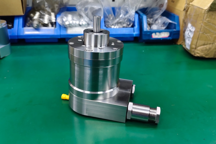
Custom Solution Photos


Encoder structure reference: 58 mm blind hollow flange, 15 mm shaft, 1 m radial cable outlet.
Signal & Output Architecture
The page defines a push-pull parallel interface with direct absolute bit output, not a network protocol. That makes controller-side mapping the key integration task.
Primary integration value: direct absolute position reading with more single-turn granularity than lower-bit versions.
Primary limitation: cable discipline and signal assignment matter more than nominal resolution. In practice, unstable readings are more likely to come from wiring or EMC than from the sensing core itself. This engineering judgment is consistent with the published direct-line parallel structure and EMC ratings.
Mechanical & Installation Focus
The 15 mm blind hollow shaft, 30 mm insertion depth, and published static/dynamic misalignment limits mean mounting precision is still the dominant mechanical factor. At 12000 rpm maximum speed, shaft tolerance and alignment have more influence on usable performance than housing size alone.
Wiring & Installation
This version uses a 1 m radial PVC cable with AWG26 conductors, 7.1 mm cable diameter, and minimum bend radius of 46 mm fixed / 61 mm flexing. Primary commissioning risk is still controller-side mapping. Practical startup order is bit sequence → Latch logic → DIR logic → power/GND reference.
Integration & Compatibility
- Designed for parallel absolute encoder systems
- Matches 58 mm blind hollow installations with 15 mm shaft
- Suitable for multi-turn position feedback without battery replacement
- Not suitable for fieldbus-based control structures or simple incremental feedback use cases
Lead Time
Typical production lead time: 15 working days. Custom adaptation can be developed around shaft fit, cable routing, signal assignment, and installation requirements.
Key Technical Data
| Item | Data |
|---|---|
| Model | OCD-PPA1G-0812-B150-CRW |
| Interface | Parallel push-pull |
| Type | Absolute multi-turn |
| Sensing | Optical |
| Resolution | 12 bit + 8 bit |
| Code | Gray |
| Multi-turn | Mechanical gear train |
| Supply | 10–30 VDC |
| Protection | IP65 |
| Flange | 58 mm blind hollow |
| Shaft | 15 mm |
| Depth | 30 mm |
| Cable | 1 m radial |
| Speed | 12000 rpm |