We developed a custom solution for model UCD-DPC1B-1213-HRSS-H72. Selected when multi-turn absolute feedback is required via Profibus, using a 58 mm blind hollow structure with a 6.35 mm (1/4") shaft, without battery-based turn counting. Typical production lead time: 15 working days. The referenced configuration uses Profibus DPV0 / DPV1 / DPV2 Class 2, magnetic sensing, 13-bit single-turn resolution, 12-bit multi-turn resolution, and a self-powered magnetic pulse counter without battery or gear train.
Key Specifications
- Interface: Profibus DPV0 / DPV1 / DPV2 Class 2
- Resolution: 13-bit single-turn + 12-bit multi-turn
- Code: Binary
- Multi-turn: self-powered magnetic counter, no battery, no gear train
- Supply: 10–30 VDC
- Protection: IP66/IP67
- Structure: 58 mm blind hollow, 6.35 mm shaft, 28 mm depth
- Speed: up to 3000 rpm
Decision Snapshot
- Best for: Profibus absolute positioning systems needing battery-free multi-turn retention
- Key fit: 6.35 mm hollow shaft, 58 mm blind hollow flange, 28 mm insertion depth
- Avoid if: the system only needs incremental feedback or is standardized on another motion-bus architecture; that follows from the listed Profibus-specific interface and bus-side wiring layout.
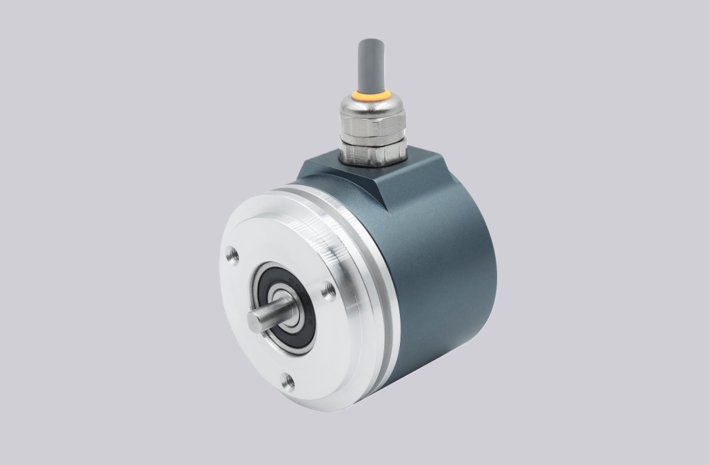
Custom Solution Photos
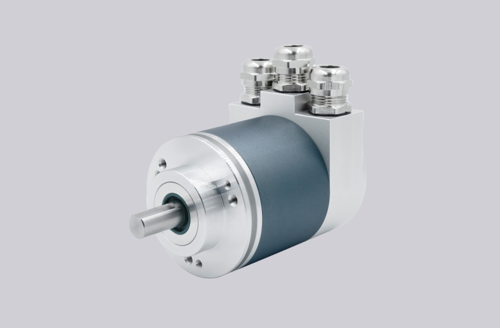
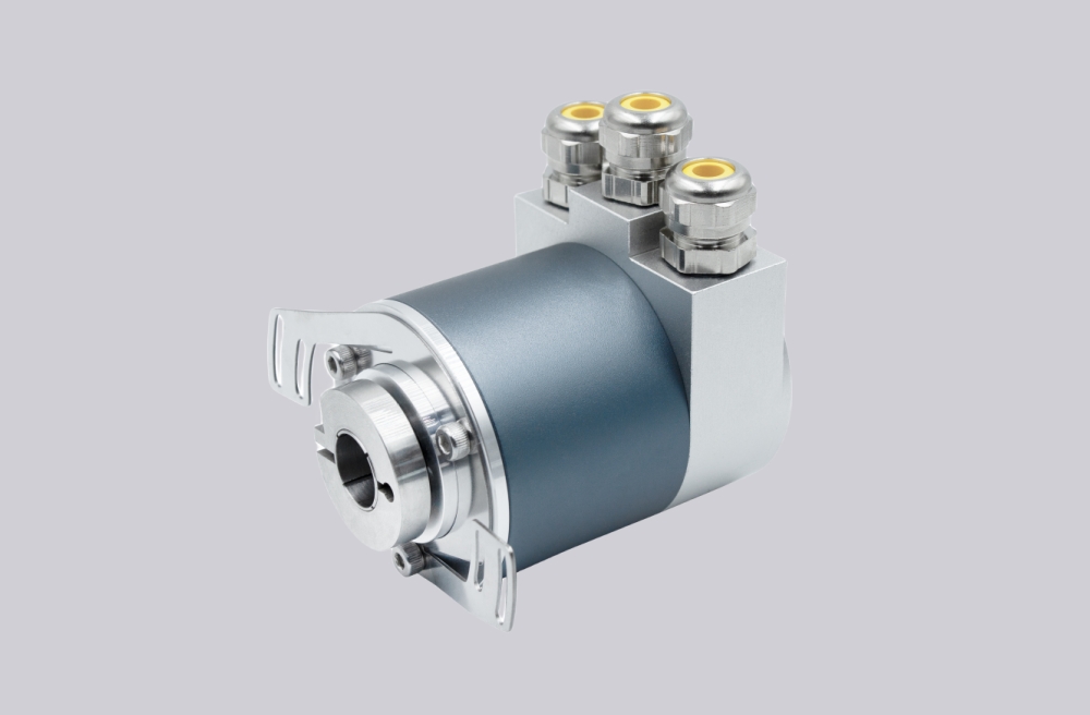
Encoder structure reference: 58 mm blind hollow flange, 6.35 mm shaft, radial M12 bus connector layout.
Bus Configuration & Communication
- Interface class: Profibus Class 2
- Transmission rate: up to 12 Mbaud
- Cycle time: ≥ 1 ms
- Functions: resolution, scaling, speed filter, preset, direction, limit switch, node number, teach mode, diagnostics
Primary integration risk: incorrect node addressing or termination-switch setup. Best practice: confirm address setting, termination status, and bus-in / bus-out continuity before power-up. That judgment is grounded in the listed address selection switch, termination DIP switch, and three-connector bus in/out layout.
Mechanical & Installation Focus
- Housing: steel with corrosion-protective coating
- Flange: aluminum, 58 mm blind hollow
- Shaft: 6.35 mm hollow, 28 mm depth
- Misalignment limits: static ±0.3 mm / ±0.5 mm, dynamic ±0.1 mm / ±0.2 mm
Primary mechanical constraint: blind hollow installation quality. Best practice: control shaft tolerance, insertion depth, and alignment stability together, not bore size alone. This matters even more on a small 1/4 inch shaft because the installation margin is narrower than on larger hollow-shaft versions. The recommendation is an engineering judgment supported by the listed misalignment limits and blind-hollow geometry.
Wiring & Bus Topology
- Connection: radial, 3 × M12 connectors
- Interface 1: M12 male, 4 pin, A-coded
- Interface 2: M12 female, 5 pin, B-coded
- Interface 3: M12 male, 5 pin, B-coded
- Signals: Power Supply, GND, Bus line A / B for bus in and bus out
Primary commissioning issue: bus topology errors. Check sequence: address → termination → bus continuity → power. This is the correct engineering check order for the published connector and signal arrangement.
Integration & Compatibility
- Designed for Profibus absolute encoder systems with configurable node and scaling functions
- Matches 58 mm blind hollow installations with 6.35 mm shaft
- Suitable for multi-turn feedback where battery-free retention is preferred
- Not suitable for incremental-only systems or non-Profibus architectures; this is a selection conclusion based on the listed interface and wiring structure.
Lead Time
Typical production lead time: 15 working days. Custom adaptation can be developed around shaft fit, connector layout, and bus commissioning requirements.
Key Technical Data
| Item | Data |
|---|---|
| Model | UCD-DPC1B-1213-HRSS-H72 |
| Interface | Profibus |
| Profile | DPV0 / DPV1 / DPV2 Class 2 |
| Type | Absolute multi-turn |
| Sensing | Magnetic |
| Resolution | 13 bit + 12 bit |
| Code | Binary |
| Multi-turn | Self-powered magnetic counter |
| Supply | 10–30 VDC |
| Protection | IP66/IP67 |
| Flange | 58 mm blind hollow |
| Shaft | 6.35 mm |
| Depth | 28 mm |
| Speed | 3000 rpm |
| Connection | 3 × M12, radial |