A custom compatible encoder solution can be provided for OCD-DPC1B-0013-B15V-H72 in maintenance, retrofit, replacement, and upgrade projects. This model is a singleturn absolute encoder with a Profibus fieldbus interface, blind hollow shaft construction, and 3×M12 connector connection, making it suitable for applications where field wiring continuity, shaft-side fit, and bus parameter consistency must be preserved together. Typical production lead time: 15 working days. The engineering target is to match the original installation logic, communication behavior, and mechanical interface so that field replacement can remain efficient and controlled.
Technical Overview of the OCD-DPC1B-0013-B15V-H72 Encoder
The OCD-DPC1B-0013-B15V-H72 is a singleturn absolute encoder using Profibus communication with DPV0, DPV1, and DPV2 Class 2 support. The interface cycle time is at least 1 ms, transmission speed is up to 12 Mbaud, and the output driver uses an optically isolated Profibus data interface. The sensor technology is optical, the code format is binary, and the singleturn resolution is 13 bit. Programming functions listed for this model include resolution, scaling factor, speed scaling plus filter, preset, counting direction, limit switch, node number, teach mode, and diagnostics mode.
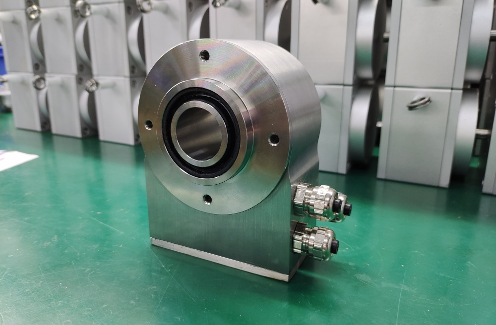
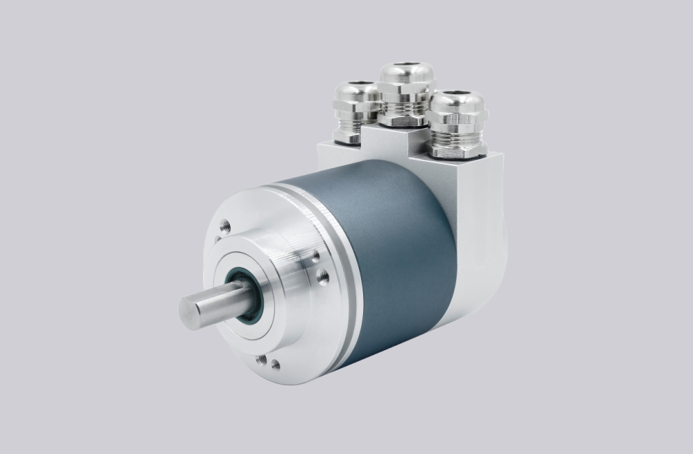
Mechanically, this version uses a blind hollow shaft with 30 mm depth and a shaft diameter of 15 mm. The flange form is a 58 mm blind hollow style, and the encoder uses stainless-steel mechanical parts with an uncoated stainless housing. The connection direction is radial, and the electrical connection uses 3×M12 connectors, which is an important point for machines where cable routing space and connector orientation are already fixed in the field.
Industrial Integration Considerations
For retrofit work, the blind hollow shaft structure is one of the most important compatibility factors. This model uses a 15 mm shaft interface with defined static and dynamic misalignment limits, so replacement planning should preserve shaft fit, insertion depth, and clamping conditions rather than focusing only on communication protocol. In field installations, blind hollow shaft encoders often depend on the original shaft engagement logic to maintain long-term alignment stability.
The Profibus side also deserves careful review. This encoder supports node addressing, diagnostics, preset handling, scaling, and direction settings, and the product description notes address selection switches and a terminal resistor switch. In practical maintenance projects, these functions matter because the existing controller and bus network may already rely on an established addressing and commissioning method. A compatible replacement solution should therefore preserve both bus communication type and parameter handling expectations.
Environmental durability is another integration point. The encoder is rated IP66/IP67 on both shaft and housing sides, with operating temperature from -40 °C to +85 °C, shock resistance up to 100 g, vibration resistance up to 10 g, and maximum mechanical speed up to 3000 rpm. These characteristics support use in industrial feedback applications where sealing, mechanical stability, and environmental tolerance need to remain consistent after replacement.
Custom Compatible Encoder Solution
A custom compatible encoder solution for OCD-DPC1B-0013-B15V-H72 should focus on five core engineering points: Profibus Class 2 communication continuity, 13-bit singleturn absolute feedback, 15 mm blind hollow shaft fit, radial 3×M12 connection layout, and preserved field parameter logic. This is important because successful replacement depends not only on nominal dimensions, but also on whether the new unit remains aligned with the original commissioning method, connector arrangement, and shaft-side installation practice.
From the electrical side, a compatible solution should maintain the 10–30 VDC supply range, optically isolated Profibus interface behavior, and the original bus in / bus out / power connection structure. From the mechanical side, it should remain consistent with the 58 mm blind hollow shaft platform, 15 mm shaft diameter, and radial connector arrangement. Where the original installation uses preset, scaling, diagnostics mode, or node addressing features, those items should be confirmed during engineering review so that installation continuity can be preserved in the field.
Custom Solution Photos


Lead Time and Custom Development
Typical production lead time: 15 working days.
For custom development, the main checkpoints should include shaft diameter, blind hollow depth, flange style, radial connector clearance, bus addressing method, and required programming functions. Since this model supports resolution setting, scaling, preset, counting direction, node number, teach mode, and diagnostics mode, the final coded configuration should be reviewed against the original application before release. This helps keep maintenance and retrofit work aligned with the installed fieldbus and mechanical setup.
Typical Technical Parameters
| Parameter | Specification |
|---|---|
| Encoder Type | Absolute encoder, singleturn |
| Model | OCD-DPC1B-0013-B15V-H72 |
| Interface | Profibus |
| Profibus Profile | DPV0, DPV1 and DPV2 Class 2 |
| Output Driver | Profibus data interface, optically isolated |
| Supply Voltage | 10–30 VDC |
| Power Consumption | ≤ 1.5 W |
| Current Consumption | ≤ 115 mA @ 10 VDC, ≤ 50 mA @ 30 VDC |
| Startup Time | < 1 s |
| Sensing Principle | Optical |
| Resolution | 13 bit |
| Code Type | Binary |
| Transmission Speed | ≤ 12 Mbaud |
| Interface Cycle Time | ≥ 1 ms |
| Programmable Functions | Resolution, scaling factor, speed scaling + filter, preset, counting direction, limit switch, node number, teach mode, diagnostics mode |
| Shaft Type | Blind hollow shaft |
| Shaft Depth | 30 mm |
| Shaft Diameter | 15 mm |
| Flange / Housing Size | Blind hollow, ø58 mm |
| Connection Type | 3 × M12 connectors |
| Connection Direction | Radial |
| Protection Rating | IP66 / IP67 |
| Operating Temperature | -40 °C to +85 °C |
| Max. Speed | ≤ 3000 1/min |
| Shock Resistance | ≤ 100 g |
| Vibration Resistance | ≤ 10 g |
| Housing Material | Stainless steel |
| Shaft Material | Stainless steel |
| Misalignment | Static ±0.3 mm / ±0.5 mm; Dynamic ±0.1 mm / ±0.2 mm |