We provide a custom compatible solution for CEV65M-00444, built to keep the original SSI absolute feedback behavior stable through the radial M23 12-pin connector. The key replacement risk is the controller-side SSI read cycle: Clock+/Clock-, Data+/Data-, Gray-code decoding, preset inputs, and connector shielding must stay consistent, or the system can receive a valid-looking but unstable position word. Typical production lead time: 15 working days.
Where the System Fails First
The controller reads CEV65M-00444 through SSI differential clock and data pairs. The pinout assigns SSI_Clock- / SSI_Clock+, SSI_Data+ / SSI_Data-, RS485 programming lines, Direction input, Preset1, Preset2, supply voltage, and ground. That makes the failure boundary clear: the SSI signal path and the control inputs must be matched before the replacement can be trusted.

The failure points are direct:
- Weak SSI clock pair → shifted or unstable position word
- Poor RS422 data shielding → intermittent read errors
- Wrong Gray-code decoding → clean signal, wrong position
- Preset1 / Preset2 mismatch → false machine reference
- Direction input error → reversed counting behavior
- Radial M23 connector strain → long-term signal instability
For CEV65M-00444, the practical replacement boundary is SSI clock integrity plus M23 connector reliability. A stable replacement must reproduce the original SSI timing behavior before mechanical fit can be considered successful.
Connector and Signal Boundary
The document defines SSI clock frequency from 80 to 1000 kHz and a typical SSI mono time of 20 µs. These values are not cosmetic. If the controller uses the wrong SSI timing window, the encoder may respond, but the absolute word can be shifted, delayed, or sampled incorrectly.
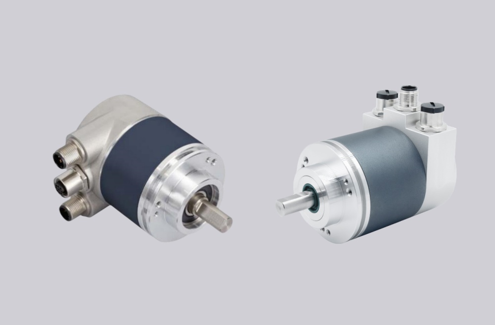
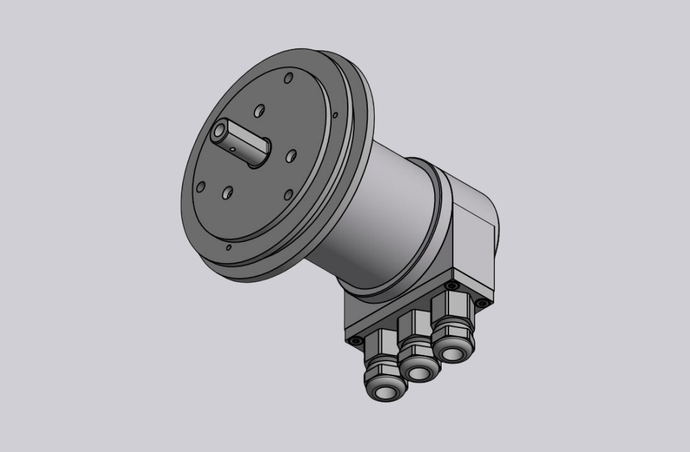
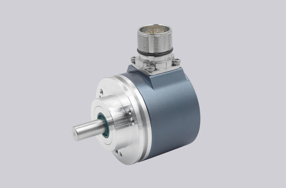
The drawing shows a ZB36 flange, 10FL / 19.5 shaft, and 12-pin M23 radial connector on the housing. This connector position is convenient for service access, but it also makes cable strain, shield continuity, and cabinet routing part of the reliability boundary. SSI failures often appear as random position instability rather than a total signal loss.
Installation Notes
- Keep the model format as CEV65M-00444
- Keep SSI Clock+ / Clock- as a clean differential pair
- Keep SSI Data+ / Data- as a clean RS422 return pair
- Match controller timing to 80–1000 kHz SSI clock and 20 µs mono time
- Confirm Gray-code decoding before startup
- Verify Direction, Preset1, and Preset2 logic
- Protect the radial M23 connector from cable strain
- De-energize the system before wiring or connector work
Key Data
- Model: CEV65M-00444
- Type: Absolute rotary encoder
- Interface: SSI
- Code: Gray
- Resolution: 4096 steps / revolution
- Multiturn range: 4096 revolutions
- Supply voltage: 11–27 VDC
- Nominal voltage: 24 VDC
- Typical current: 80 mA unloaded
- Output level: RS422
- SSI clock frequency: 80–1000 kHz
- SSI mono time: 20 µs
- Flange: ZB36
- Shaft: 10FL / 19.5
- Connector: M23 / CONTACT 12-pin
- Connector position: Radial on housing
- Protection: IP65
- Temperature range: 0–60 °C
- Options: F/R, Preset 1+2, Programmable
- Pinout: 185E
- Parameter file: CE831-095
- Firmware: 437860