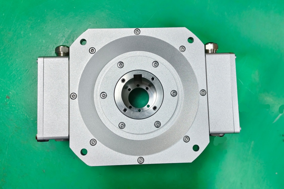
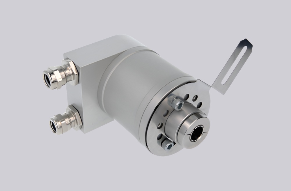
For M6-5S3XH51-T003, EncoderWorks can configure a custom compatible replacement solution only if the 1 1/8 inch hollow-shaft bore, end-of-shaft mounting, 12–24 VDC line driver, XH output-side order, 1024 PPR high-range output from the 51 base PPR code, T conduit-box terminal connection, torque-arm modification, hazardous-area marking, clamping-collar fit, anti-rotation bracket movement, A/B signal mapping, and 150 kHz frequency margin remain matched. The main failure boundary is an explosion-protected hollow-shaft feedback system that produces pulses but develops wrong speed scaling, inactive-output wiring, phase reversal, voltage-level mismatch, housing wobble, bearing wear, terminal-box faults, or hazardous-area sealing risk because the bore, output side, line driver, torque arm, grounding path, or protection construction has changed. Typical production lead time: 15 working days.
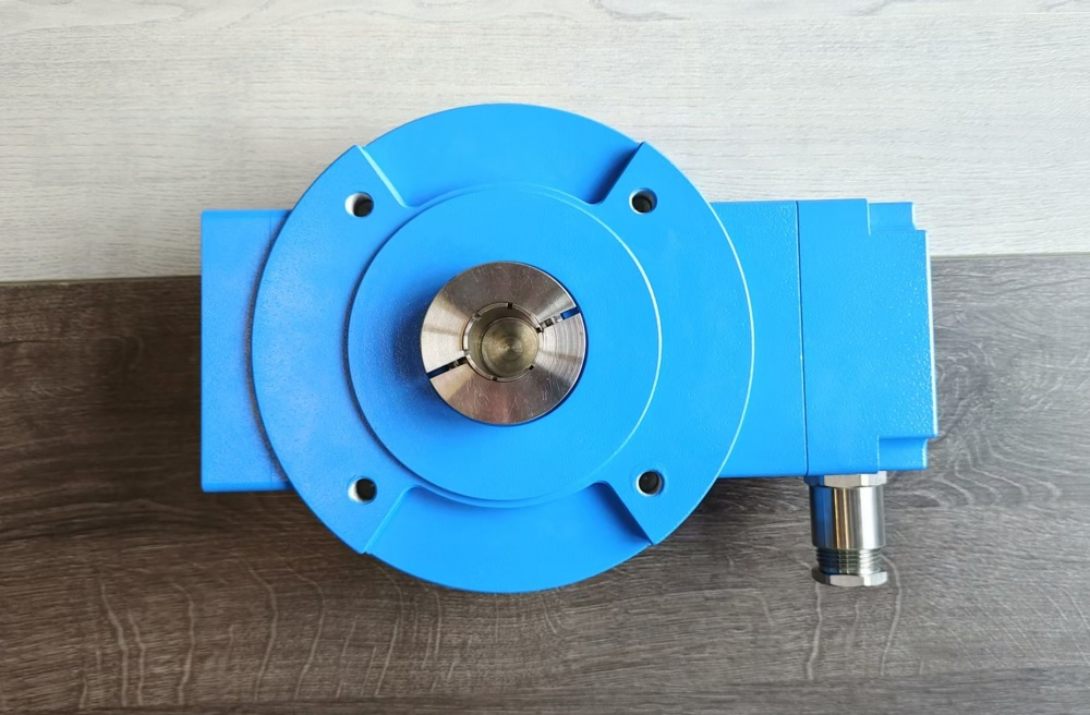
This model belongs to the M6 explosion-protected hollow-shaft incremental encoder platform. The 5 bore code points to a 1 1/8 inch shaft interface, while the S mounting code indicates end-of-shaft installation with a clamping collar and flexible anti-rotation bracket. The 3 line-driver code should be treated as a 12–24 VDC configuration. The XH output range indicates that one output side is unused and the other output side uses the high range; with base PPR code 51, the active high-range output is 1024 PPR. The T connection indicates a conduit box with terminal block and 3/4 inch NPT entry, and the 003 modification indicates torque-arm configuration.
System Limits
The first system limit is XH output-side order. This model should not be treated as identical to an HX version unless the installed terminal schedule confirms that the active high-range output is connected to the same controller input. If the active side is reversed, the controller may receive no feedback, receive the wrong output side, or fail a drive feedback check even when the PPR and voltage level are correct.
The second limit is 1024 PPR high-range scaling with a 12–24 VDC line driver. If the drive input is configured for 512, 600, 960, 1200, or another pulse value, the encoder may output clean square waves while speed, position, or process feedback becomes wrong. Controller input voltage, load condition, signal format, edge-counting mode, and 150 kHz frequency margin should be confirmed before production.
The third limit is hollow-shaft and torque-arm stability. The 1 1/8 inch bore must match the motor shaft tolerance, the encoder must slide onto the shaft without force, and the clamping collar must be tightened evenly. Excessive shaft runout, insufficient shaft engagement, damaged clamping fingers, uneven collar tightening, rigid torque-arm mounting, or excessive housing movement can create vibration, bearing stress, signal degradation, and reduced service life.
Wiring & Installation
Before replacement, verify the nameplate code, hazardous-area marking, bore size, XH output arrangement, base PPR, marker requirement, T terminal-box arrangement, 12–24 VDC line-driver requirement, and torque-arm modification. Confirm which output side is wired to the drive or controller, because an XH version should not be treated as interchangeable with HX or HH without checking the installed terminal schedule.
During mechanical installation, clean the motor shaft, check for burrs or damage, and do not tighten the clamping collar before the encoder is placed on the shaft. The encoder should slide on smoothly. The torque arm or anti-rotation bracket should prevent housing rotation while allowing shaft end float, and it must not turn the encoder into a rigidly mounted device.
For signal stability, use individually shielded wire pairs where required, keep feedback wiring away from power cables and switching devices, and maintain proper grounding at the specified grounding location. In hazardous-area service, do not wire while energized, do not open the housing in a hazardous environment, use suitable certified cable-entry hardware, and verify the IP66 sealing boundary after installation.
Custom Compatible Solution
EncoderWorks can configure the replacement around the installed explosion-protected hollow-shaft interface:
- Match the 1 1/8 inch hollow-shaft bore, end-of-shaft mounting, clamping-collar fit, torque-arm geometry, and anti-rotation bracket behavior
- Preserve the active high-range 1024 PPR output from the 51 base PPR code, XH output-side order, A/B phase behavior, marker or no-marker requirement, and controller input compatibility
- Review the 12–24 VDC line-driver requirement, T conduit-box terminal wiring, grounding path, shielded cable routing, hazardous-area marking, and IP66 entry sealing
- Check shaft engagement, shaft runout, collar tightening, housing wobble, bearing load, active-output routing, and torque-arm modification before shipment
Key Data
| Item | Data |
|---|---|
| Model | M6-5S3XH51-T003 |
| Encoder type | Explosion-protected hollow-shaft incremental encoder |
| Series | M6 |
| Bore code | 5 |
| Bore size | 1 1/8 inch |
| Mounting style | S, end-of-shaft mounting |
| Line driver | 3, 12–24 VDC |
| Output range | XH, one side none / one side high range |
| Base PPR code | 51 |
| Effective PPR | 1024 PPR on the active high-range output |
| Marker | Not shown in code; confirm if Z/Z- is required |
| Connector | T, conduit box terminal block, 3/4 inch NPT |
| Modification | 003, torque arm |
| Hazardous-area marking | Ex de IIC T4 Gb boundary for M6 series |
| Protection class | IP66 |
| Frequency range | 0–150 kHz for M6 series |
| Key replacement checks | 1 1/8 inch bore fit, XH output-side order, active 1024 PPR output, 12–24 VDC line driver, NPT terminal mapping, torque arm, clamping collar, grounding, hazardous-area sealing |