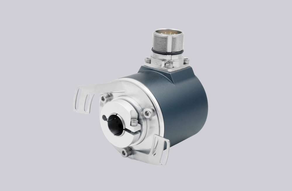
EncoderWorks builds the PVM78E-011DRR0BI-1212 custom compatible replacement solution around explosion-proof PROFIBUS DP multiturn feedback where node address, bus termination, 24-bit position structure, DR terminal-compartment wiring, dual cable-gland sealing, INOX housing grounding, and Ø10 mm clamping-flange coupling must remain aligned with the installed PLC project. The failure boundary is not only the 10–30 VDC supply, but also GSD compatibility, Class 2 scaling, preset behavior, counting direction, Bus IN / Bus OUT A/B polarity, PE continuity, shield termination, stainless enclosure fit, and explosion-proof certificate scope. Typical production lead time: 15 working days.
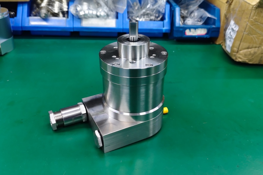
This model is used where the controller reads absolute multiturn position over a PROFIBUS DP network from a solid-shaft encoder with a radial DR terminal compartment and stainless housing. A compatible replacement must preserve the 12-bit singleturn and 12-bit multiturn position structure, binary code behavior, node address setting, termination logic, terminal mapping, Ø10 mm shaft interface, clamping-flange fit, and hazardous-area installation boundary.
System Limits
The first system boundary is the PROFIBUS DP configuration and 24-bit scaling structure. PVM78E-011DRR0BI-1212 must appear to the PLC as the same PROFIBUS encoder device with the correct node address, GSD file behavior, Class 2 parameter structure, scaling function, preset function, counting direction, diagnostic response, and 24-bit position expectation. If the replacement is installed with the wrong address, different overall resolution, incorrect preset behavior, mismatched direction, or incompatible parameter mapping, the bus may still detect a device while the axis reports the wrong position, reversed travel, incorrect multiturn value, or unstable commissioning diagnostics.
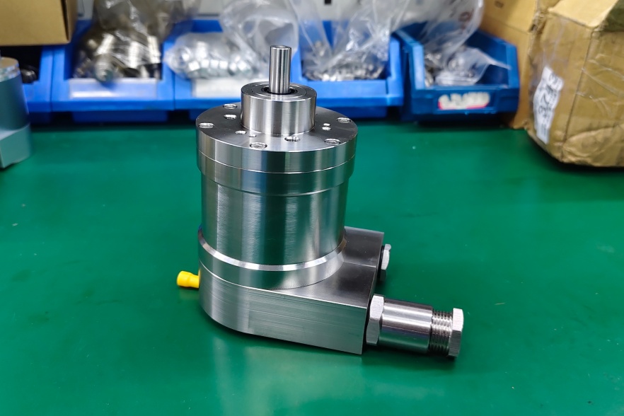
The second boundary is the DR terminal compartment and INOX clamping-flange installation. Bus IN and Bus OUT A/B polarity, supply reference, GND, PE, shield path, terminal-resistor status, two cable glands, cable strain relief, terminal sealing, and stainless housing grounding must remain consistent with the field wiring. A correct encoder can still fail if the terminal resistor is enabled at the wrong point, the outgoing bus is interrupted, A/B is reversed, the shield is terminated with high impedance, or one cable gland is not sealed correctly. Mechanically, the Ø10 mm × 20 mm solid shaft, clamping flange, coupling alignment, axial load, radial load, and radial terminal clearance must be checked together.
Wiring & Installation
Before replacement, confirm the full installed model code, PROFIBUS node address, GSD requirement, 12-bit singleturn and 12-bit multiturn structure, Class 2 scaling use, preset requirement, counting direction, diagnostic mapping, DR terminal layout, radial cable-entry direction, terminal-resistor position, and INOX housing requirement. This DR stainless version should not be inferred from K2, K5, KA, KR, or aluminum-housing variants because the field wiring, dual cable-gland sealing, Bus IN / Bus OUT routing, shield termination, and enclosure grounding boundary are different.
During installation, verify Terminal 1 / 2 supply wiring and Bus IN / Bus OUT A/B assignment before powering the system. Keep PROFIBUS wiring away from motor and drive cables, maintain large-surface shield continuity, and avoid cable kinking, tensile load, or shearing load at each cable gland. The clamping flange should seat flat, and the coupling should not force the Ø10 mm shaft off center. Explosion-proof suitability must be confirmed against the installed hazardous-area requirement and certificate scope before shipment.
Custom Compatible Solution
- Match PROFIBUS DP behavior, 12-bit singleturn plus 12-bit multiturn feedback, binary code, node address, and Class 2 parameter expectations
- Preserve GSD compatibility, overall scaling, preset, counting direction, diagnostic behavior, Bus IN / Bus OUT A/B mapping, PE, and shield continuity
- Adapt the Ø10 mm × 20 mm solid shaft, clamping flange, DR terminal compartment, two cable glands, INOX stainless housing, and IP66 sealing boundary
- Review bus termination, terminal grounding, cable-gland sealing, coupling alignment, shaft load, hazardous-area certificate scope, and commissioning requirements before shipment
Key Data
| Item | Data |
|---|---|
| Model | PVM78E-011DRR0BI-1212 |
| Encoder type | Explosion-proof absolute multiturn rotary encoder |
| Interface | PROFIBUS DP |
| Profile | PROFIBUS encoder profile 3.062, Class 1 / Class 2 |
| Supply voltage | 10–30 VDC |
| Output code | Binary |
| Singleturn resolution | 12 bit |
| Multiturn resolution | 12 bit |
| Total position structure | 24-bit absolute multiturn data |
| Connection | DR, terminal compartment with 2 cable glands |
| Cable exit | R, radial |
| Shaft / flange | Ø10 mm × 20 mm solid shaft, clamping flange |
| Housing material | I, INOX stainless steel |
| Protection class | IP66 sealing boundary requires confirmation against installed version |
| Hazardous-area boundary | ATEX / IECEx explosion-proof compliance requires confirmation against installed certificate scope |
| Key replacement checks | Node address, bus termination, GSD file, Class 2 scaling, preset, direction, Bus IN / Bus OUT A/B, PE, shield continuity, DR terminal sealing, INOX grounding, Ø10 mm clamping-flange coupling |