When replacing GXP2W.A4021A2, the EncoderWorks custom compatible replacement should first control SSI cable-output mapping, 13/12-bit position programming, and Ø10 mm IP65 clamping-flange alignment. This model should not be handled like the radial M23 connector version. The 21 cable-output code moves the main risk from plug pin matching to conductor assignment, shield handling, preset wiring, and SSI pair integrity.
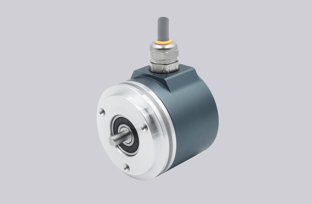
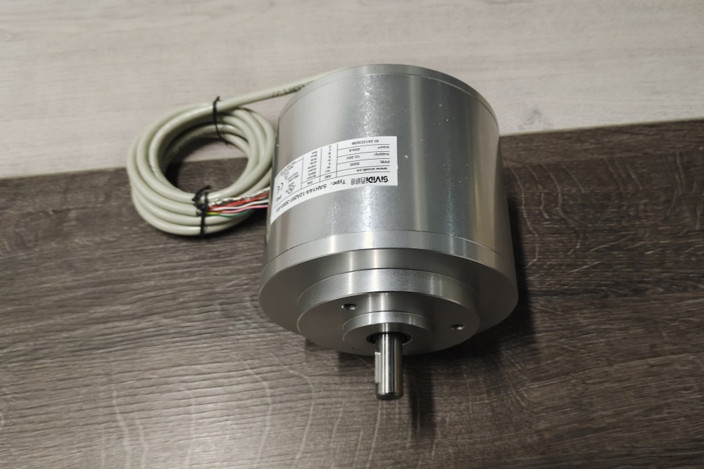
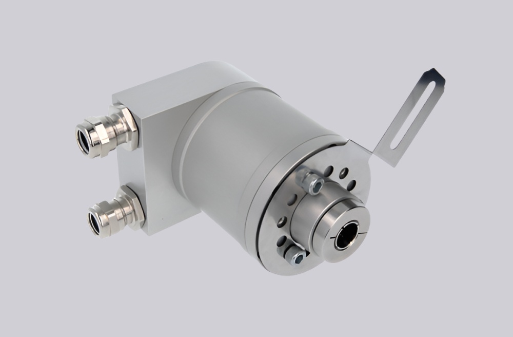
The GXP2W.A4021A2 is an SSI multiturn absolute encoder with optical sensing, 13-bit singleturn resolution, 12-bit multiturn range, 8192 steps per turn, 4096 turns, 10–30 VDC supply, SSI RS485 data output, RS232 programming interface, Ø58 mm housing, Ø10 mm clamping flange, IP65 shaft-seal execution, and 1 m radial cable connection.
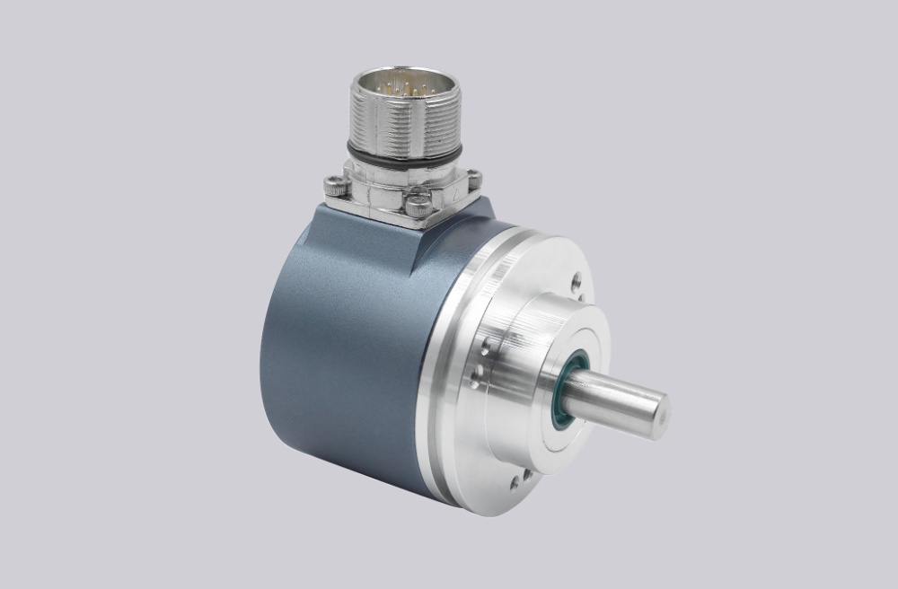
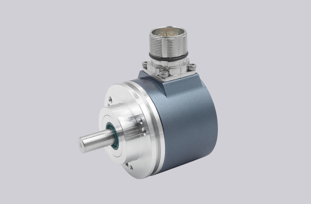
The first failure boundary is SSI cable mapping. Data+/Data- and Clock+/Clock- must remain paired correctly, especially when the cable is extended through a cabinet or junction box. If the shield, clock pair, or data pair is wired as ordinary conductors, the controller can receive a shifted or unstable SSI word even when the encoder output stage is healthy.
This replacement fails when SSI communication is present, but the PLC reads intermittent or incorrect multiturn values because cable pair assignment, clock frequency, shield grounding, or SSI timing does not match the original installation. That is a signal-chain failure, not an encoder sensing failure.
The second boundary is programmed position behavior. Total resolution, Gray or binary code, rotating direction, preset, offset, and zero point must match the previous encoder. A replacement with the correct cable and shaft can still return the wrong absolute position if the original programmed parameters are not copied.
Preset and UP/DOWN inputs must also be controlled. Preset changes the electrical zero, while UP/DOWN changes direction logic. A wrong input state can create a stable but incorrect position value. Unused inputs should be tied or protected according to the machine’s wiring practice, not left undefined.
Mechanically, the Ø10 mm clamping flange requires clean coupling alignment. IP65 protection does not correct radial preload, axial load, or cable strain. The radial cable exit should have enough bend radius so the cable does not pull on the housing or disturb shielding.
The replacement decision should first confirm Ø10 mm clamping-flange geometry, IP65 shaft-seal requirement, 1 m radial cable assignment, SSI Clock+/Clock- and Data+/Data- pairing, 13-bit singleturn and 12-bit multiturn mapping, Gray/binary setting, UP/DOWN direction, preset behavior, RS232 programmed parameters, supply voltage, shielding, and coupling load. EncoderWorks treats GXP2W.A4021A2 as an industrial encoder custom compatible solution where SSI cable integrity and clamping-flange mechanics decide field reliability.
Typical production lead time: 15 working days.
Key Data
| Item | Data |
|---|---|
| Model | GXP2W.A4021A2 |
| Encoder type | Multiturn absolute encoder |
| Interface | SSI |
| Sensor technology | Optical |
| Resolution | 13-bit singleturn + 12-bit multiturn |
| Steps / turns | 8192 steps per turn / 4096 turns |
| Code | Gray or binary, programmable |
| Supply voltage | 10–30 VDC |
| Housing | Ø58 mm steel housing |
| Shaft / flange | Ø10 mm clamping flange |
| Protection class | IP65 with shaft seal |
| Connection | 1 m radial cable |
| Programming interface | RS232 |
| Main engineering anchor | SSI cable output and clamping flange |
| Main failure boundary | Wrong SSI pair mapping, code mismatch, preset error, coupling preload |