When replacing FGHJ40K-2048G-90G-NG/20P, EncoderWorks focuses its custom compatible solution on the 200 kHz frequency ceiling, NG reference stability, and HTL edge margin under inverter noise. This model is not difficult because it has 2048 PPR; it becomes difficult when the machine speed, cable length, counter input filter, and shield grounding together reduce the real usable signal margin.
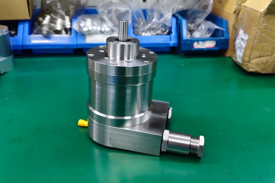
The FGHJ40K-2048G-90G-NG/20P is an incremental hollow-shaft encoder with 2048 pulses per revolution, G output, 90° quadrature, NG reference pulse with inverted signal, K terminal-box connection, and /20P hollow-shaft mounting. The FGHJ execution also indicates electrically isolated bearing construction, which is normally used where shaft current from inverter-fed motors must not pass through the encoder bearing system.
The first replacement checkpoint is frequency headroom. A 2048 PPR encoder produces twice the pulse density of a 1024 PPR version at the same shaft speed. That does not automatically make it unsuitable, but it changes the counter margin. The controller input must accept the actual edge rate with enough reserve, especially when quadrature evaluation, input filtering, or long cable capacitance is involved. A replacement should not be approved only because the pulse count matches the nameplate.
This replacement fails when the encoder output still looks normal at low speed, but the drive counter begins to miss edges near operating speed because the 2048 PPR signal has pushed the system closer to its frequency, cable, or input-filter limit. In many field cases, the encoder is blamed first, while the real weak point is the receiving counter or the wiring environment.
The NG reference pulse adds a second failure boundary. At 2048 PPR, the reference pulse must remain clean and correctly assigned because it is often used for homing, reset, position confirmation, or synchronization. If the NG signal is noisy, inverted incorrectly, or delayed relative to the A/B channels by wiring or receiver behavior, the machine may run continuously but fail during restart, reference search, or position validation.
The 90° quadrature relationship also needs to be verified under motion, not only at standstill. Direction recognition depends on the phase order between the basic channel and the 90° channel. When the edge rate increases, marginal shield grounding or cable routing close to motor leads can disturb one channel more than the other. The result may be intermittent direction uncertainty rather than a permanent fault.
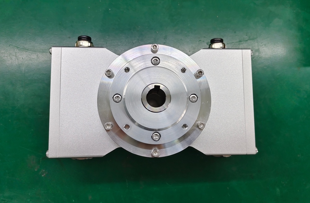
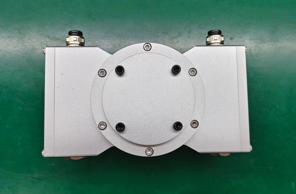
Mechanically, the /20P hollow shaft must be mounted without forcing the encoder body into position. The torque bracket should stop rotation while allowing small shaft movement to be absorbed without bearing preload. The isolated-bearing structure helps against shaft-current damage, but it does not solve poor runout, axial stress, or bracket misalignment. On higher pulse-density feedback, mechanical vibration can also appear as signal instability at the controller.
The K terminal box gives room for proper wiring, but it demands disciplined installation. The cable pairs should preserve signal pairing, shield termination should be short and controlled, and the grounding strap should connect to a clean low-impedance machine point. In VFD environments, the replacement must be checked as an electrical system: encoder output, cable, shield, counter input, and grounding path.
For this model, the replacement decision must first confirm 2048 PPR frequency margin, NG reference behavior, A/B phase sequence, isolated-bearing continuity, /20P hollow-shaft fit, and EMC-safe terminal-box wiring. EncoderWorks treats FGHJ40K-2048G-90G-NG/20P as an industrial encoder custom compatible replacement where the main risk is not making pulses, but keeping every edge usable at the controller.
Typical production lead time: 15 working days.
Key Data
| Item | Data |
|---|---|
| Model | FGHJ40K-2048G-90G-NG/20P |
| Encoder type | Incremental hollow-shaft encoder |
| Bearing execution | Electrically isolated bearing version |
| Pulse rate | 2048 PPR |
| Signal format | G output with 90° quadrature |
| Reference pulse | NG, with inverted signal |
| Output type | Push-pull / HTL-style line driver |
| Supply voltage | 12–30 VDC |
| Connection | K terminal box |
| Hollow shaft | /20P |
| Main engineering anchor | 200 kHz frequency ceiling and NG stability |
| Main failure boundary | Missed counter edges, noisy NG reference, weak shield grounding |