EncoderWorks develops a concise custom compatible solution for CEV65M-11021, focused on preserving Profibus-DP feedback while matching the ZB80 bearing-module alignment. The replacement fails when bus settings are correct but shaft load, shielding, or bearing-module support is treated like a standard short-body encoder.
Where the System Fails First
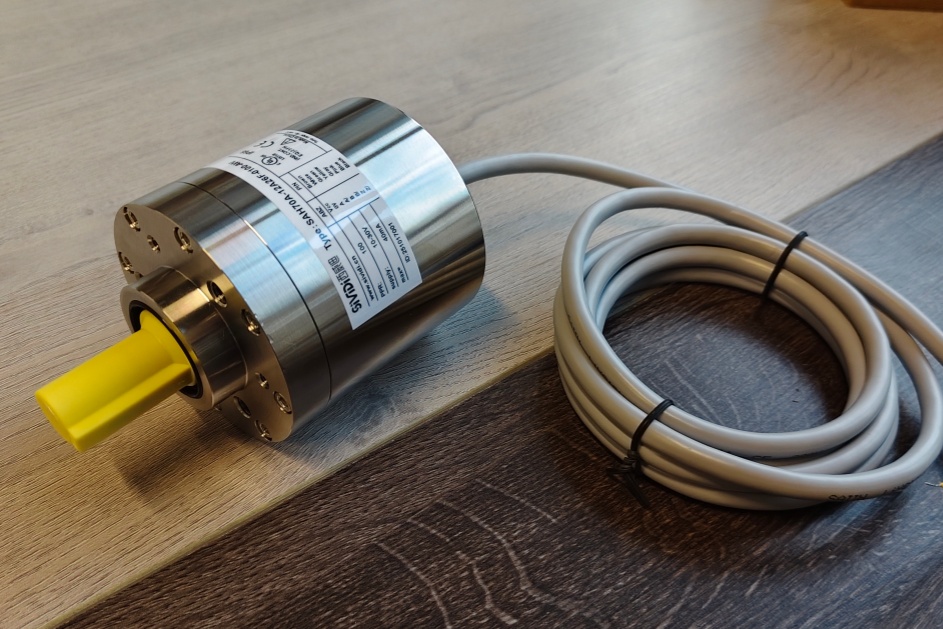
The controller reads CEV65M-11021 as a Profibus-DP absolute encoder with PNO Profile Class 2 behavior. The document defines 8192 steps per revolution, 4096 revolutions, programmable code, RS485 output level, 12 Mbaud option, and a 3 × PG9 radial fieldbus connection. For this model, the replacement boundary is stricter than a standard compact Profibus encoder because the bearing module changes the mechanical failure point.
This replacement fails when the Profibus node is restored correctly but the bearing-module alignment or shaft loading is treated like a normal short-body encoder.
The first checks are direct. Wrong station address makes the PLC lose the node. Wrong S3/S4 termination creates intermittent bus faults. Reversed DataA / DataB stops stable communication. Weak shield contact inside the PG hood creates telegram errors under EMC load. But for CEV65M-11021, the mechanical side must also be checked early: the bearing module, ZB80 flange, and 10FL / 19.5 shaft must sit without coupling stress.
A stable replacement must first reproduce the original Profibus address, termination state, shield path, and bearing-module mechanical support before the position value can be trusted.
Bearing Module and Fieldbus Boundary
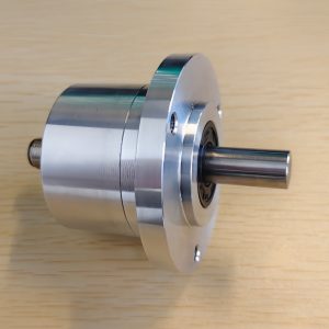
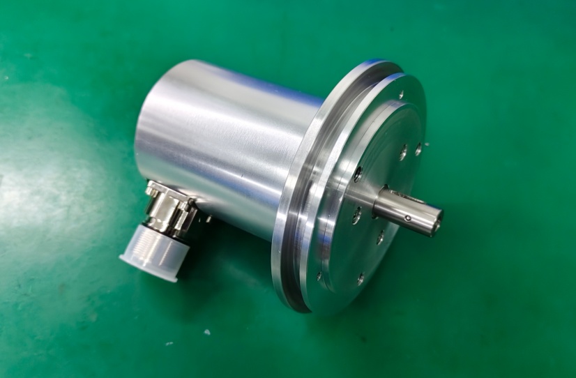
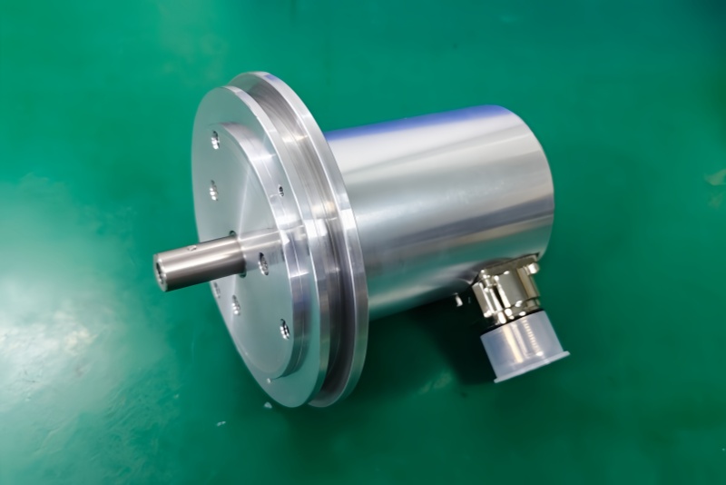
The drawing shows a long body structure with ZB80 centering, 3 × PG7/PG9 radial cable entries, a visible 2-LED window, shielding screw point, and a bearing-module style housing. This is not just a connector hood. It is the point where bus-in, bus-out, supply, preset inputs, shielding, termination, and mechanical support meet.
The pinout note states that if the encoder is the last station in the Profibus line, S3 and S4 must be switched on; otherwise they must remain off. The station address is set from 3 to 99 by BCD address switches. These settings should be copied from the old installation before commissioning.
Installation Notes
- Keep the model format as CEV65M-11021
- Restore the original Profibus station address before startup
- Use S3/S4 termination only when this encoder is the last bus station
- Wire DataA / DataB exactly as defined
- Keep PG radial hood shielding continuous
- Check bearing-module alignment before judging encoder failure
- Confirm ZB80 flange and 10FL / 19.5 shaft fit
- Verify bus topology before replacing the encoder body
Key Data
- Model: CEV65M-11021
- Type: Absolute rotary encoder
- Interface: Profibus DP
- Profile: PNO Profile Class 2
- Resolution: 8192 steps / revolution
- Multiturn range: 4096 revolutions
- Code: Programmable
- Output level: RS485
- Supply voltage: 11–27 VDC
- Option: 12 Mbaud
- Mechanical option: Bearing module
- Flange: ZB80
- Shaft: 10FL / 19.5
- Connector: 3 × PG9
- Connector position: PG radial
- Protection: IP65
- Operating temperature: -20 °C to +70 °C
- Pinout: TR-ECE-TI-GB-0017
- Drawing: 04-CEV65M-M0960
- Firmware: 437826