


We provide a custom compatible solution for CEV65M-01976, built to keep the original Profibus-DP feedback behavior stable during replacement. The key field risk is not only matching the encoder body; it is preserving PNO Profile Class 2 behavior, station address setting, S3/S4 termination, DataA/DataB wiring, and PG radial hood shielding so the PLC continues to read the same absolute position without bus diagnostics. Typical production lead time: 15 working days.

Where the System Fails First
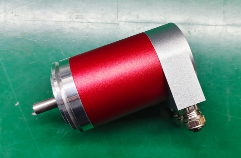
The controller reads CEV65M-01976 as a Profibus-DP absolute encoder. The document defines 4096 steps per revolution, 4096 revolutions, programmable code, RS485 output level, 12 Mbaud option, PNO Profile Class 2, and 3 × PG9 radial cable entries. For replacement, the first checkpoint is the Profibus layer: address, termination, cable routing, shield bonding, and incoming/outgoing bus continuity.
The failure points are direct:
- Wrong station address → PLC cannot identify the encoder
- S3/S4 termination set incorrectly → intermittent bus fault
- DataA / DataB reversal → no stable communication
- Poor PG hood shield bonding → telegram errors under EMC
- Preset1 / Preset2 wiring mismatch → wrong machine reference
- Bus cable not matched to Profibus use → unstable diagnostics
For CEV65M-01976, the practical replacement boundary is Profibus address and termination discipline. If the encoder is the last station, S3 and S4 must be switched on; otherwise they must remain off. A replacement can be mechanically correct and still fail if this bus condition is wrong.
Fieldbus Hood and Mechanical Boundary
The drawing shows a ZB50 flange, 12FL / 24 shaft, and 3 × PG9 radial cable entries. This fieldbus hood is where the real system risk sits: bus-in, bus-out, supply, preset inputs, shielding, and termination all meet in the same connection area. A loose shield clamp or wrong cable path can make the encoder look defective while the root cause is the bus topology.
Mechanically, the 12FL / 24 shaft and ZB50 flange must match the original installation, but Profibus commissioning should be checked first. The PLC must see the same station behavior before shaft fit can be judged as a successful replacement.
Installation Notes
- Keep the model format as CEV65M-01976
- Match the alternative reference 110-01976 where required
- Set the Profibus station address before commissioning
- Use S3/S4 termination only when the encoder is the last bus station
- Wire DataA / DataB exactly as defined
- Keep PG radial hood shielding continuous
- Verify Preset1 and Preset2 input logic
- Check bus topology before replacing the encoder body
Key Data
- Model: CEV65M-01976
- Alternative reference: 110-01976
- Type: Absolute rotary encoder
- Interface: Profibus DP
- Profile: PNO Profile Class 2
- Resolution: 4096 steps / revolution
- Multiturn range: 4096 revolutions
- Code: Programmable
- Output level: RS485
- Supply voltage: 11–27 VDC
- Option: 12 Mbaud
- Flange: ZB50
- Shaft: 12FL / 24
- Connector: 3 × PG9
- Connector position: PG radial
- Protection: IP65
- Temperature range: 0–60 °C
- Pinout: TR-ECE-TI-D-0017
- Drawing: 04-CEV65M-M0166
- Software No.: 4376AA


