


The custom compatible solution for CEV65M-10737 is built around a single failure point: the controller must read the parallel absolute word without bit shift, latch error, or TELDIX connector instability. This model is not difficult because of resolution; it is difficult because O_D0–O_D23 mapping, latch timing, direction input, preset wiring, and the 90° angled connector all have to behave correctly at the same time. Typical production lead time: 15 working days.
This is a parallel push-pull absolute encoder, not SSI, Profibus, PROFINET, CANopen, or incremental feedback. The signal does not travel as one serial data stream. It is read as a full parallel word. One wrong bit line is enough to make the position value wrong while the encoder still appears electrically normal.
Where the System Fails First
The pinout defines O_D0 to O_D23 as data outputs. These 24 lines must be mapped exactly at the controller input. Parallel feedback usually does not fail like a lost fieldbus node. It fails as a corrupted bit, unstable sampled value, or position jump caused by poor latch timing.
The real weak points are direct:
- Wrong O_D0–O_D23 mapping → corrupted absolute value
- Latch timing error → sampled transition state
- Weak TELDIX shield contact → bit-level noise
- Wrong Direction input → reversed position logic
- Preset1 / Preset2 wiring error → false machine reference
- RS485 programming wires mixed with output wiring → commissioning fault
The document lists BUS, F/R, Latch, Preset 1+2, and Programmable options. These are not accessory features. They define how the controller reads, freezes, reverses, presets, and interprets the absolute position word.
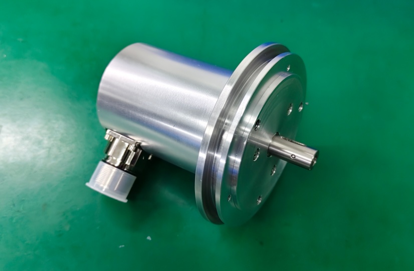
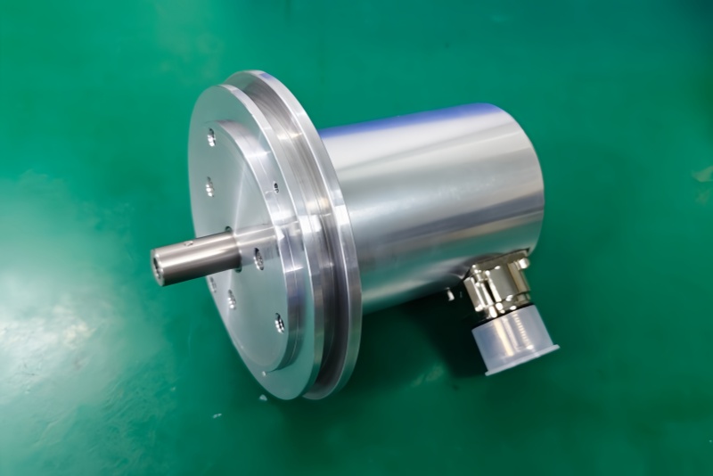
Connector and Mechanical Boundary
The drawing shows a ZB80 flange, 12FL / 24 shaft, and a 39-pin TELDIX connector in 90° angled position. That angled connector is part of the failure boundary. If the connector is loaded by cable pull, cabinet clearance, or vibration, the first symptom may be random bit errors rather than a complete signal loss.
The larger flange and shaft give stronger mechanical support, but the feedback stability still depends on coupling alignment and connector strain relief. A mechanically normal encoder can still deliver wrong data if the 39-pin connector shield or latch input is unstable.
Installation Notes
- Keep the model format as CEV65M-10737
- Map O_D0–O_D23 before checking anything else
- Confirm latch timing at the controller side
- Verify Direction, Preset1, and Preset2 logic before startup
- Do not activate BUS/DataBus control unless tristate behavior is intended
- Keep the 90° TELDIX connector free from side load
- Separate parallel wiring from inverter and motor power cables
- De-energize the system before wiring or connector work
Key Data
- Model: CEV65M-10737
- Type: Absolute rotary encoder
- Interface: Parallel push-pull
- Code: Programmable
- Resolution: 4096 steps / revolution
- Multiturn range: 4096 revolutions
- Supply voltage: 11–27 VDC
- Output level: 11–27 VDC
- Flange: ZB80
- Shaft: 12FL / 24
- Connector: 39-pin TELDIX
- Connector position: 90° angled
- Protection: IP65
- Temperature range: -20 °C to +70 °C
- Options: BUS, F/R, Latch, Preset 1+2, Programmable
- Pinout: ST138B
- Parameter file: CE833-265
- Firmware: 43770D


