


The custom compatible solution for CEV65M-02497 is built around one problem: the controller must read a wide parallel absolute value cleanly. For this model, the main risk is not encoder resolution. It is O_D0–O_D23 bit mapping, latch timing, TELDIX connector stability, preset wiring, and direction logic. Typical production lead time: 15 working days.
This is not SSI, Profibus, PROFINET, or incremental feedback. It is a parallel push-pull absolute output. That means every bit line matters. One wrong input, one floating wire, or one badly timed latch signal can corrupt the whole position value while the encoder still appears to be working.

Where the System Fails First
The pinout defines O_D0 to O_D23 as data outputs. These lines must be mapped exactly at the controller side. Parallel output does not usually fail as a clean communication loss. It often fails as a wrong bit, unstable sampled value, or position jump when the PLC reads during a transition.
The real field risks are direct:
- Wrong O_D0–O_D23 mapping → corrupted absolute value
- Latch timing error → unstable position capture
- Weak TELDIX shield contact → bit-level noise
- Wrong Direction input → reversed position logic
- Preset1 / Preset2 wiring error → false machine reference
- RS485 programming wires mixed with data wiring → commissioning fault
The document lists F/R, Latch, Preset 1+2, and Programmable options. These are not secondary functions. They decide whether the controller reads the right absolute value after startup, replacement, or preset operation.
Connector and Timing Boundary
The 39-pin TELDIX connector is the system boundary. The encoder may be normal, but a loose connector shell, weak strain relief, or poor shield path can create random bit errors. A short cable helps, but it does not remove cabinet-side EMC risk. Keep the parallel data wiring away from inverter output lines, relay coils, and motor power cables.
The latch input is the part most likely to be underestimated. If the controller samples while the output word is changing, the fault looks like encoder instability. In reality, the controller is reading at the wrong moment.
Installation Notes
- Keep the model format as CEV65M-02497
- Map O_D0–O_D23 before checking anything else
- Confirm latch timing before replacing the encoder
- Verify Direction, Preset1, and Preset2 logic
- Keep TELDIX shielding and cable strain relief solid
- Separate parallel data wiring from power and inverter cables
- De-energize the system before connector work
Key Data
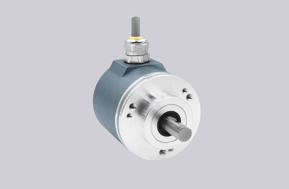
- Model: CEV65M-02497
- Type: Absolute rotary encoder
- Interface: Parallel push-pull
- Code: Programmable
- Resolution: 4096 steps / revolution
- Multiturn range: 4096 revolutions
- Supply voltage: 11–27 VDC
- Output level: 11–27 VDC
- Flange: ZB36
- Shaft: 10FL / 19.5
- Connector: 39-pin TELDIX
- Cable length: 0.5 m
- Connector position: PG axial
- Protection: IP65
- Temperature range: -20 °C to +70 °C
- Options: F/R, Latch, Preset 1+2, Programmable
- Pinout: ST138B
- Parameter file: CE833-265
- Firmware: 437865


