A custom compatible replacement for 14-1436X-250 can be supplied by EncoderWorks with the main check placed on 10–30 V RS422 receiver matching, 250 PPR controller scaling, and ATEX keyed-shaft load. This model should not be grouped with 256 PPR or 300 PPR versions. The pulse count is close, but a small scaling mismatch can still create wrong speed, distance, or angular feedback.
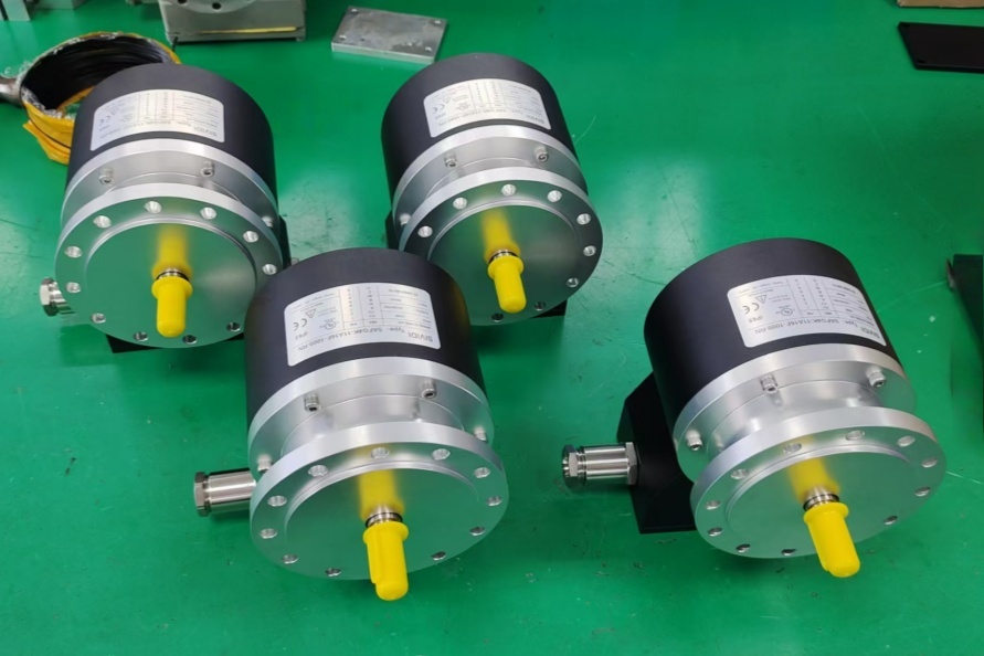
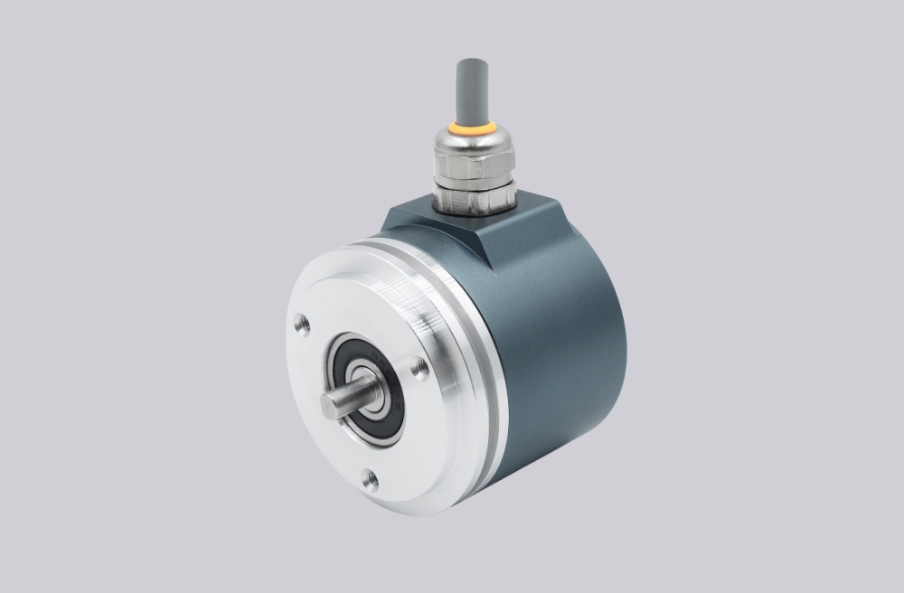
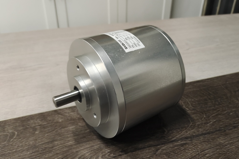
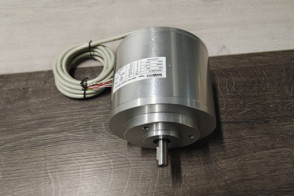
The 14-1436X-250 is an ATEX incremental rotary encoder configuration with photoelectric sampling, 250 PPR, 10–30 V RS422 output switching, A/B/0 plus inverted signal channels, IP66 protection, Ø12 mm keyed shaft, clamping flange, and 9-core 2 m cable connection. At 250 PPR, frequency overload is usually less critical than exact counter setup and reference-pulse handling.
The first failure boundary is controller scaling. If the PLC or drive remains configured for 256, 300, 500, or another pulse count, the encoder can produce clean A/B signals while the calculated motion value is wrong. Quadrature mode, direction logic, and 0-channel reference use must match the original installation.
This replacement fails when A/B/0 signals are stable, but the controller calculates the wrong motion value because 250 PPR scaling, quadrature evaluation, or reference-pulse logic does not match the original encoder. That is a configuration failure, not a sensing failure.
The second boundary is RS422 signal mapping. A/A-, B/B-, and 0/0- must be wired as differential pairs. A crossed inverted channel can reduce noise immunity, disturb direction validation, or make homing unreliable even when basic counting still appears normal.
Mechanically, the Ø12 mm keyed shaft and clamping flange must be checked with the coupling, pulley, or measuring wheel. ATEX suitability, PE shield connection, cable route, and axial/radial shaft-load limits remain part of the replacement decision.
The replacement decision should first confirm ATEX marking, Ø12 mm keyed shaft fit, clamping-flange centering, 250 PPR scaling, 10–30 V RS422 receiver compatibility, A/B/0 plus inverted channel mapping, 100 kHz output-frequency margin, shield grounding, cable route, and shaft load. EncoderWorks treats 14-1436X-250 as an industrial encoder custom compatible solution where RS422 mapping and exact 250 PPR scaling decide field reliability.
Typical production lead time: 15 working days.
Key Data
| Item | Data |
|---|---|
| Model | 14-1436X-250 |
| Encoder type | ATEX incremental rotary encoder |
| Detection type | Photoelectric sampling |
| Pulse count | 250 PPR |
| Output switching | 10–30 V RS422 |
| Signal output | A, B, 0 and inverted A, B, 0 |
| Supply voltage | 10–30 VDC |
| Output frequency | Max. 100 kHz |
| Shaft / flange | Ø12 mm keyed shaft, clamping flange |
| Connection | 9-core cable, 2 m |
| Protection class | IP66 |
| Main engineering anchor | RS422 scaling and ATEX shaft load |
| Main failure boundary | Wrong scaling, receiver mismatch, inverted-pair error, shaft overload |