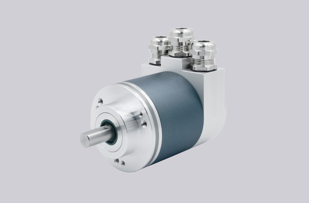
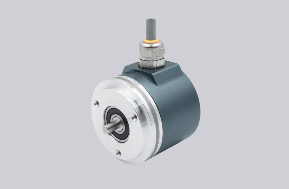
We developed a custom solution for the GA241.B126102 encoder, intended for applications where stable 13-bit binary parallel absolute position output must be maintained under industrial noise, direct PLC input structures, and synchro-flange mounting conditions. This configuration is based on the GA241 singleturn parallel absolute encoder platform, using a synchro flange, Ø6 mm solid shaft, 10–30 VDC supply, and binary push-pull parallel output. It is not a serial interface device and it is not tolerant of loose control logic. It is a parallel data system where STORE, ENABLE, UP/DOWN, and Zero setting must be integrated correctly or the position word becomes unreliable. Typical production lead time: 15 working days.
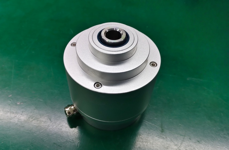
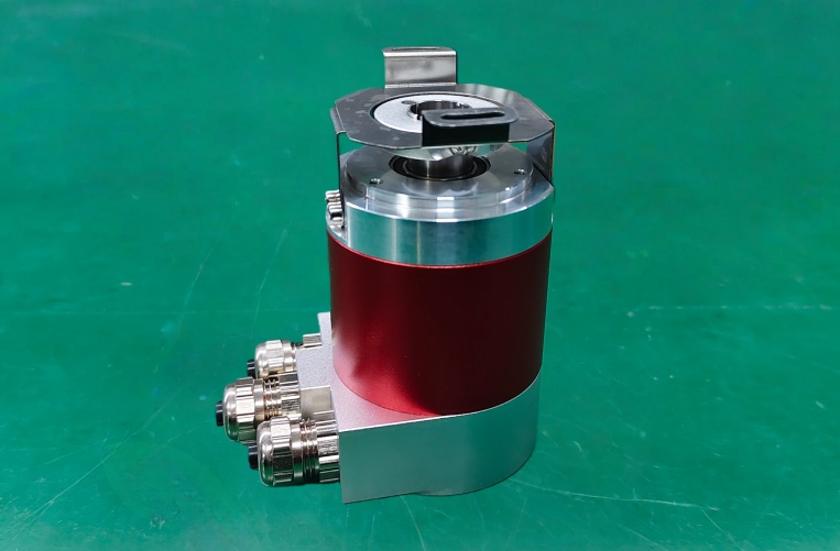
Custom Solution Photos

Stable operation depends on shaft alignment, synchro flange rigidity, connector integrity, and clean parallel signal handling.
System Limits
- No STORE signal during readout → position data can change during sampling
- ENABLE not held active → outputs switch to high-impedance and appear lost
- Weak shielding or noisy parallel wiring → bit errors and unstable absolute values
The GA241 platform is a 13-bit optical singleturn parallel encoder with 8192 steps per turn, push-pull short-circuit-proof outputs, and permanent code continuity check. Its core value is deterministic parallel data output, but its main system boundary is still the signal chain. If the controller does not latch data correctly or if the 13 data lines are exposed to interference, the system can show false position values even when the encoder itself is mechanically normal.
This model uses binary code, which is straightforward for direct PLC interpretation, but binary output is less tolerant of asynchronous bit transitions than Gray code. For that reason, the STORE line is not optional in real control systems. The datasheet explicitly states that this line must be applied for reliable data readout in binary code.
Installation and Wiring Constraints
- Use rigid synchro flange mounting and maintain proper shaft alignment
- Use the STORE input to latch data before reading
- Keep ENABLE at active low during output operation
- Define UP/DOWN correctly to match the real shaft direction
- Return Zero setting to GND after setting for best interference immunity
- Shield all D0 to D12 data lines and control lines in noisy environments
Failure boundary:
- Missing STORE logic → unstable binary readout
- ENABLE high → no usable output
- Wrong UP/DOWN logic → reversed position behavior
- Poor shielding → corrupted parallel word
- Excess shaft load or misalignment → reduced mechanical reliability
Replacement and Interface Mapping
- Suitable for systems requiring 13-bit binary parallel absolute position feedback
- Applicable where synchro flange mounting and Ø6 mm shaft are required
- Not suitable where serial interfaces are expected or where parallel timing cannot be controlled
- Best used in control systems that can manage latch, enable, and direction logic correctly
Key Data
- Model: GA241.B126102
- Type: Singleturn absolute encoder, parallel
- Sensing method: Optical
- Resolution: 13 bit / 8192 steps
- Code: Binary
- Output circuit: Push-pull, short-circuit proof
- Supply voltage: 10–30 VDC
- Initializing time: typ. 20 ms
- Accuracy: ±0.025°
- Shaft: Ø6 mm solid shaft
- Flange: Synchro flange
- Max speed: ≤10000 rpm mechanical / ≤6000 rpm electrical
- Shaft load: ≤20 N axial / ≤40 N radial
- Protection: IP54 without shaft seal / IP65 with shaft seal
- Operating temperature: -25 to +85 °C
- Housing: Ø58 mm aluminium
GA241.B125102 Absolute Encoder
GA241.B12C102 Encoder Solution
GA241.B106102 Industrial Encoder
GA241.B10C002 Absolute Encoder Solution