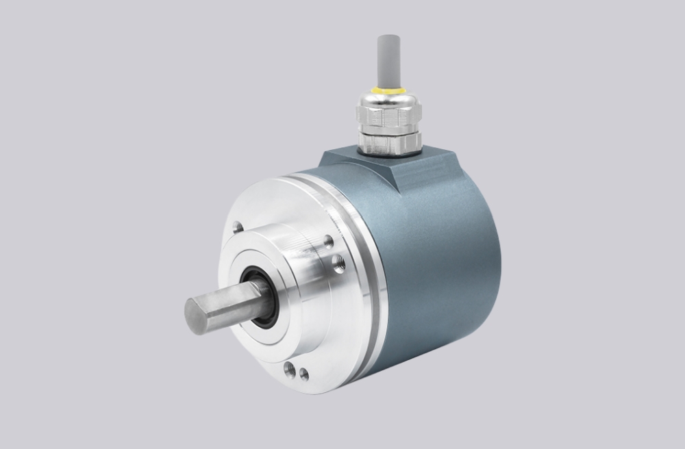
We developed a custom solution for the GA241.B10C002 encoder, intended for applications where 13-bit binary parallel absolute position output must remain stable in standard industrial environments with direct PLC input and fixed-cable installation. This configuration is based on the GA241 singleturn parallel absolute encoder platform, using a synchro flange, Ø6 mm solid shaft, 10–30 VDC supply, and binary push-pull output through a 21-core cable, in the IP54 version. It is not a serial encoder and it is not tolerant of loose control logic. It is a parallel data system where STORE timing, ENABLE control, and cable-level signal integrity determine whether the output remains usable. Typical production lead time: 15 working days.
Custom Solution Photos
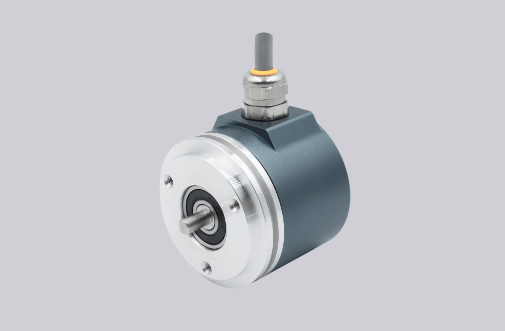

Stable operation depends on shaft alignment, synchro flange rigidity, cable integrity, and controlled parallel signal handling.
System Limits
- No STORE signal during readout → data changes during sampling
- ENABLE not active → output enters high-impedance (no signal)
- Weak cable routing or EMC noise → bit errors in parallel data
The GA241 platform provides 13-bit (8192 steps) optical singleturn output with push-pull drivers and code continuity monitoring. In this cable-based configuration, the actual system bottleneck is parallel signal synchronization across 13 data lines under EMC exposure, not encoder resolution. Even with a mechanically stable encoder, improper cable shielding or routing will directly result in incorrect absolute position values at the PLC level.
This model uses binary code, which allows direct PLC mapping but requires strict read timing control. Without STORE-based synchronization, binary output cannot be reliably sampled during rotation, leading to intermittent position jumps even when the encoder itself is functioning normally.
Installation and Wiring Constraints
- Use rigid synchro flange mounting and maintain shaft alignment
- Use STORE input to latch position data before reading
- Keep ENABLE active (Low) for valid output
- Protect the 21-core cable from crushing, repeated flexing, and uncontrolled EMC exposure
- Define UP/DOWN logic according to real shaft rotation
- Return Zero setting to GND after use for maximum interference immunity
Failure boundary:
- Missing STORE → unstable binary readout
- ENABLE inactive → no output
- Poor cable routing or shielding → corrupted parallel word
- Wrong UP/DOWN logic → reversed position behavior
- Excess shaft load or misalignment → reduced mechanical reliability
Replacement and Interface Mapping
- Suitable for systems requiring 13-bit binary parallel absolute feedback with cable output
- Applicable where synchro flange mounting, Ø6 mm shaft, and IP54 configuration are sufficient
- Not suitable where serial communication is expected or where parallel timing and cable routing cannot be controlled
- Best used in systems with strict control over latch timing, enable logic, and EMC conditions
Key Data
- Model: GA241.B10C002
- Type: Singleturn absolute encoder, parallel
- Sensing method: Optical
- Resolution: 13 bit / 8192 steps
- Code: Binary
- Output circuit: Push-pull, short-circuit proof
- Supply voltage: 10–30 VDC
- Initializing time: typ. 20 ms
- Accuracy: ±0.025°
- Shaft: Ø6 mm solid shaft
- Flange: Synchro flange
- Connection: 21-core cable
- Max speed: ≤10000 rpm mechanical / ≤6000 rpm electrical
- Shaft load: ≤20 N axial / ≤40 N radial
- Protection: IP54
- Operating temperature: -25 to +85 °C
- Housing: Ø58 mm aluminium
GA241.B126102 Absolute Encoder
GA241.B12C002 Encoder Solution
GA241.B106102 Industrial Encoder
GA241.B10C102 Absolute Encoder