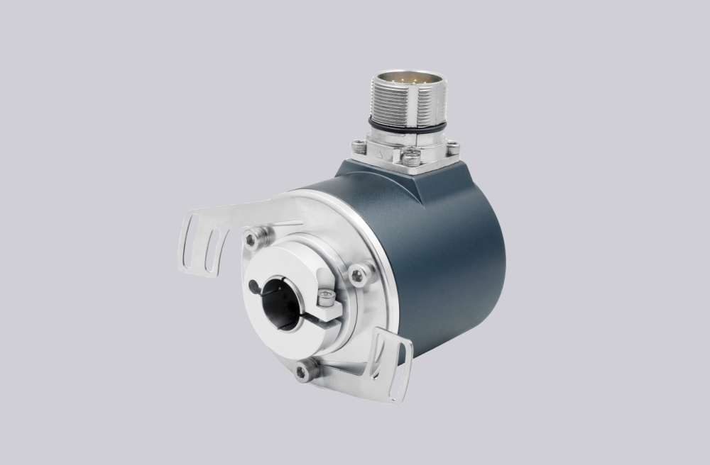



When replacing FGHJ40S-1024G-90G-NG/20P, EncoderWorks can configure a custom compatible replacement solution only if the 1024 PPR standard scaling, J isolated-bearing construction, S single 15-pole EMC industrial plug layout, /20P hollow-shaft fit, A/B 90° phase relationship, inverted signal pairs, N reference pulse behavior, torque bracket freedom, adapter-shaft run-out, and shield grounding remain unchanged. The main failure boundary is a hollow-shaft drive that receives pulses but shows wrong speed scaling, direction reversal, zero-reference loss, plug-side signal faults, or bearing-current damage because the isolation boundary, plug pin mapping, bore fit, or EMC path has changed. Typical production lead time: 15 working days.
This model belongs to the FGHJ 40 incremental hollow-shaft encoder platform. The 1024 PPR value is a standard square-wave pulse rate, so replacement work should focus on reference scaling, S plug assignment, A/B/N signal continuity, shield bonding, and controlled hollow-shaft mounting. The J construction adds an isolation boundary for installations where shaft currents or circulating currents may otherwise pass through the encoder bearings. It should not be treated as a non-isolated FGH40 encoder, an SS dual-plug version, a KK dual-terminal-box version, or an older FGHJ 4 configuration with different frequency limits.
System Limits
The first system limit is 1024 PPR standard scaling. If the controller is configured for 1000, 1200, 2048, or another pulse value, the encoder may output stable square waves while speed, travel, and synchronization values become wrong. Edge-counting mode, gear ratio, speed conversion, direction logic, and reference scaling should be checked before startup.
The second limit is S single EMC plug mapping. The 15-pole plug must preserve A, /A, B, /B, N, and /N exactly as expected by the receiving counter. If one phase pair is swapped, one inverted signal is omitted, one shield reference is weak, or the N reference pulse is assigned to the wrong pin, the machine may fail during homing, direction reversal, or synchronized positioning.
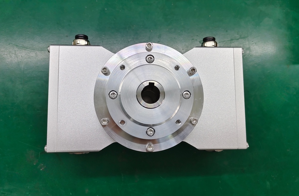
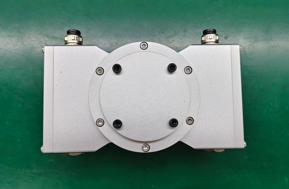
The third limit is hollow-shaft mechanics and isolated bearing protection. The /20P interface must fit the prepared shaft without forcing, and the torque bracket must remain free at the link heads. Excessive adapter-shaft run-out, axial preload, radial load, shaft shock, torque-arm binding, or loss of isolation can shorten bearing life and appear as pulse jitter or intermittent reference errors.
Wiring & Installation
Before replacement, document the 15-pole EMC plug assignment for supply voltage, GND, shield, A/B/N signal sequence, inverted outputs, and any error or diagnostic output used by the control system. Confirm that the counter input is scaled for 1024 PPR and that the system expects the same 0°/90° phase sequence and N reference pulse behavior.
During mechanical installation, clean the customer shaft, centering surface, bolting faces, and fastening threads. Align the adapter shaft carefully, avoid hammering the encoder, and do not pull the hollow-shaft device into position by force. The torque bracket should support housing reaction torque without transmitting bending load into the bearings.
For EMC stability, route feedback wiring away from inverter, motor, brake, contactor, and power cables. Use shielded cable, maintain large-area shield contact, and connect the grounding strap to a nearby low-impedance bare-metal grounding point. After commissioning, verify pulse count, direction, N reference pulse, plug seating, shield continuity, isolation requirement, and stable operation through the required speed range.
Custom Compatible Solution
EncoderWorks can configure the replacement around the installed isolated hollow-shaft and single-plug interface:
- Match 1024 PPR square-wave incremental output with 0°/90° channel behavior and inverted signal pairs
- Preserve J isolated-bearing construction, S single 15-pole EMC industrial plug layout, N reference pulse behavior, supply range, and output level
- Adapt the FGHJ 40 /20P hollow-shaft interface, adapter-shaft fit, torque bracket position, sealing boundary, and plug orientation
- Review 200 kHz counter margin, shielded wiring, plug pin mapping, grounding strap, isolation requirement, bearing load, and marker repeatability
Key Data
| Item | Data |
|---|---|
| Model | FGHJ40S-1024G-90G-NG/20P |
| Encoder type | Incremental hollow-shaft encoder |
| Series | FGHJ 40 |
| Bearing construction | Isolated bearings |
| Connection structure | S single 15-pole EMC industrial plug |
| Pulses per revolution | 1024 PPR |
| Pulse-rate class | Standard pulse rate |
| Signal output | Square wave, 0° and 90° channels |
| Inverted signals | Yes, G output configuration |
| Reference pulse | NG, N reference pulse with inverted signal |
| Hollow-shaft interface | /20P |
| Supply voltage | 12–30 VDC |
| Output type | Current-limited, short-circuit-proof push-pull line driver |
| Maximum frequency | 200 kHz, higher on request |
| Protection class | IP65 standard, IP66 versions depending on sealing |
| Mechanical checks | /20P shaft fit, adapter-shaft run-out, torque bracket freedom, bearing load, isolation boundary |
| Key replacement checks | 1024 PPR scaling, isolated bearings, single EMC plug mapping, A/B phase, N reference pulse, shield grounding |
Related Models
- FGHJ4KK-2048G-90G-NG/20P Hollow-Shaft Encoder with Isolated Dual-Box Feedback
- FGHJ4K-2048G-90G-NG/20P Hollow-Shaft Encoder with Isolated Terminal-Box Feedback
- FGHJ40KK-2048G-90G-NG/20P Hollow-Shaft Encoder with Isolated Dual-Box Feedback
- FGHJ40K-2048G-90G-NG/20P 200 kHz Frequency Ceiling and NG Stability