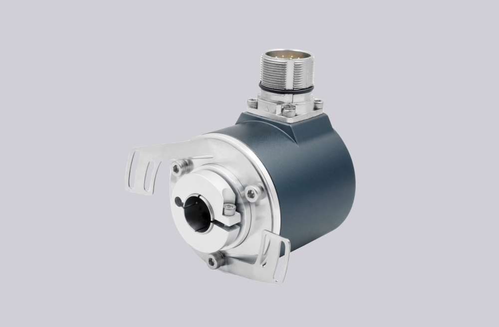
For 14-14361-1800, EncoderWorks can provide a custom compatible replacement focused on 10–30 V push-pull receiver matching, 1800 PPR counter margin, and ATEX keyed-shaft alignment. This model should not be handled like the lower-pulse 500 or 512 PPR versions. At 1800 PPR, the controller input, cable length, input filter, quadrature mode, and real shaft speed must be checked together.
The 14-14361-1800 is an ATEX incremental rotary encoder configuration with photoelectric sampling, 1800 PPR, 10–30 V push-pull output, A/B/0 plus inverted signal channels, IP66 protection, Ø12 mm keyed shaft, clamping flange, and 9-core 2 m cable connection. The 100 kHz output-frequency limit can become relevant in faster applications.
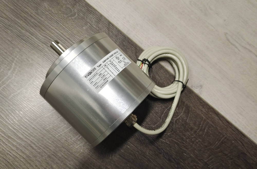
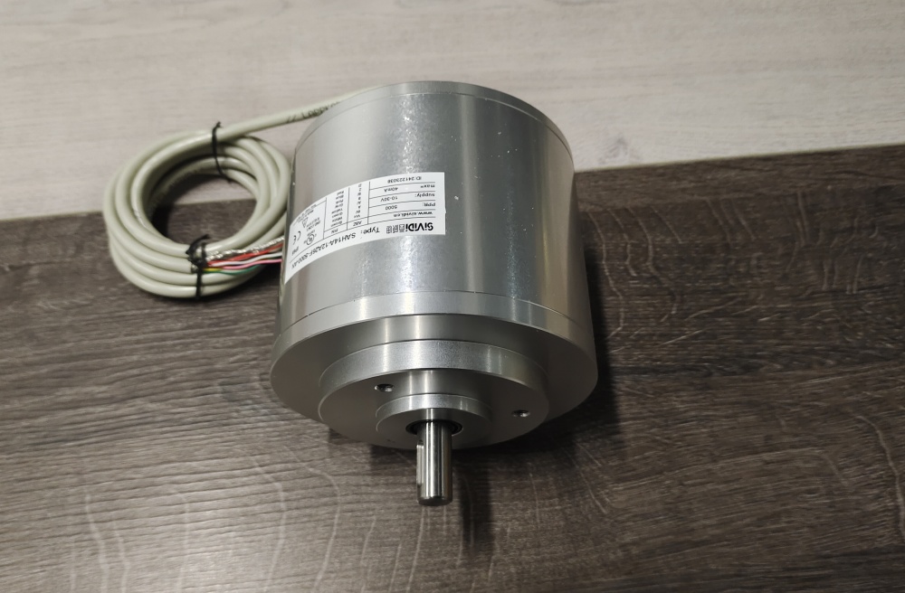
The first failure boundary is edge-frequency margin. If the shaft speed and quadrature evaluation push the counter near its usable input limit, A/B signals can appear clean at slow speed but lose edges during production. Cable capacitance and receiver input filtering can reduce the practical margin further.
This replacement fails when A/B/0 signals are visible, but the controller misses counts because 1800 PPR, operating speed, push-pull input threshold, or input filtering exceeds the real signal margin. That is a signal-chain failure, not simply an encoder failure.
The second boundary is push-pull channel mapping. A, B, 0 and inverted A, B, 0 must be wired by function. Wrong inverted-channel wiring can weaken noise rejection, direction validation, or reference-pulse detection even when basic speed feedback appears normal.
Mechanically, the Ø12 mm keyed shaft and clamping flange must be checked with the coupling, pulley, or measuring wheel. ATEX suitability, PE shielding, cable routing, axial load, and radial load remain part of the replacement decision.
The replacement decision should first confirm ATEX marking, Ø12 mm keyed shaft fit, clamping-flange centering, 1800 PPR counter setup, 10–30 V push-pull receiver compatibility, A/B/0 plus inverted channel mapping, 100 kHz output-frequency margin, shield grounding, cable route, operating speed, and shaft load. EncoderWorks treats 14-14361-1800 as an industrial encoder custom compatible solution where push-pull edge margin and keyed-shaft mechanics decide field reliability.
Typical production lead time: 15 working days.
Key Data
| Item | Data |
|---|---|
| Model | 14-14361-1800 |
| Encoder type | ATEX incremental rotary encoder |
| Detection type | Photoelectric sampling |
| Pulse count | 1800 PPR |
| Output switching | 10–30 V push-pull |
| Signal output | A, B, 0 and inverted A, B, 0 |
| Supply voltage | 10–30 VDC |
| Output frequency | Max. 100 kHz |
| Shaft / flange | Ø12 mm keyed shaft, clamping flange |
| Connection | 9-core cable, 2 m |
| Protection class | IP66 |
| Main engineering anchor | Push-pull margin and keyed shaft |
| Main failure boundary | Edge loss, receiver mismatch, inverted-channel error, shaft overload |