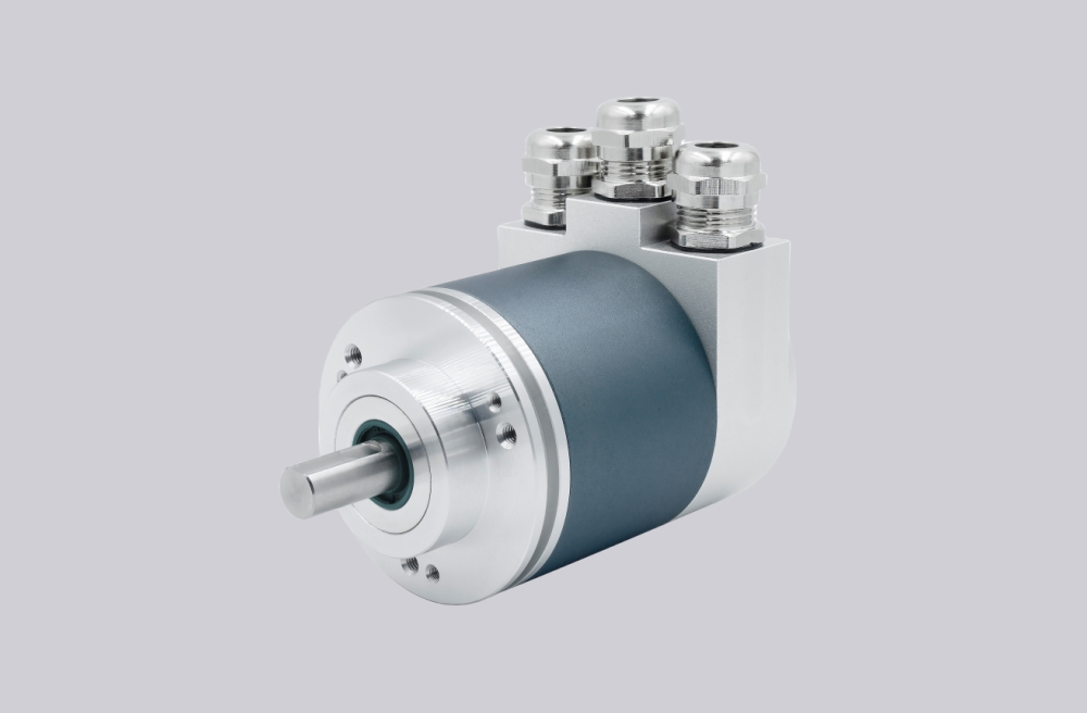
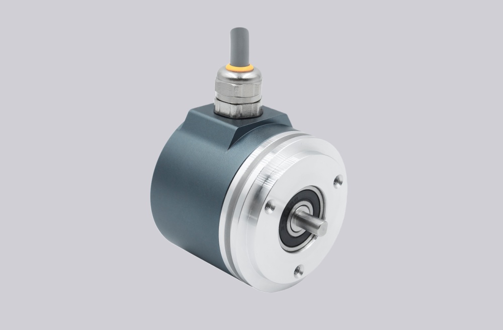
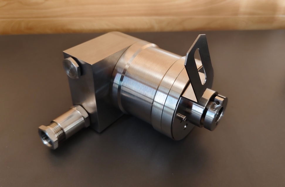
RS485 remains a widely used interface in industrial encoder systems due to its strong noise immunity, stable differential communication, and ability to support multi-device bus structures. However, many field issues are not caused by the encoder itself, but by incorrect wiring, poor bus topology, or missing termination.
RS485 communication is based on a differential signal pair, typically labeled A/B or T,R+ and T,R-. This signal structure improves resistance to electromagnetic interference, especially in environments with motors, inverters, and switching power systems. For this reason, the signal lines should always be wired using twisted-pair cable, particularly when the cable length exceeds several meters or runs close to high-power lines.
One of the most important principles is that RS485 should be wired as a bus, not a star network. Devices must be connected sequentially along the line. Star wiring introduces reflections and signal distortion, which can lead to unstable communication, especially at higher baud rates.
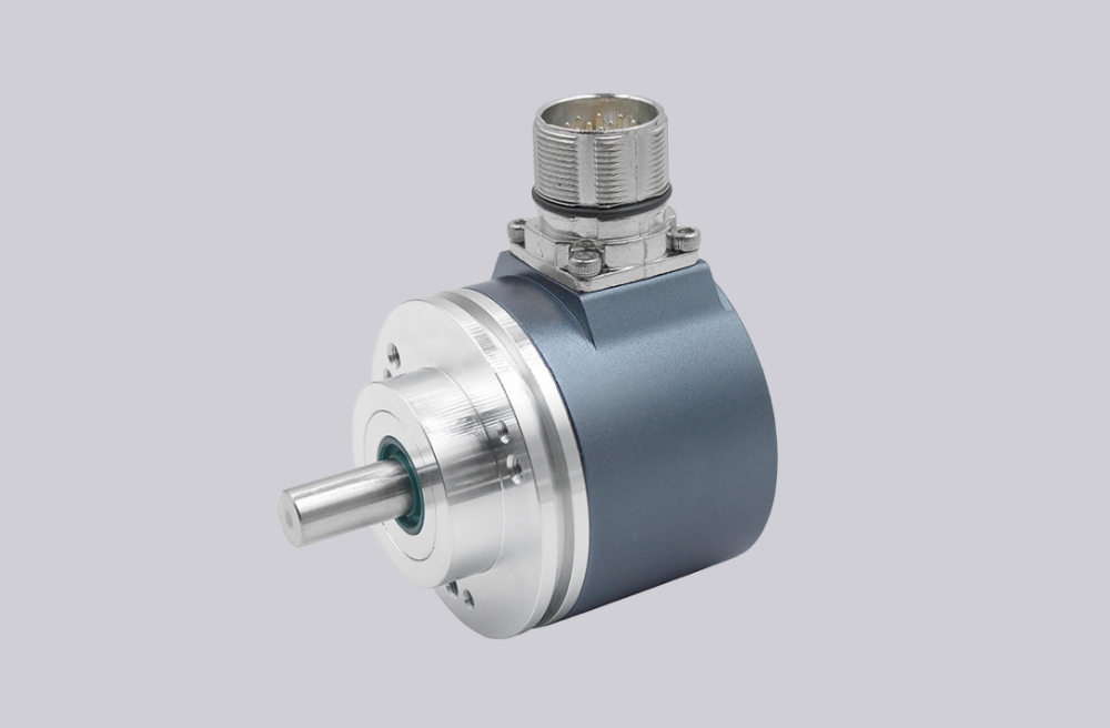
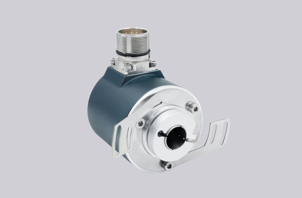
Termination is another critical point. A termination resistor (typically 120–150 Ω) should be placed at the ends of the bus, not at every device. In encoder systems, the most common issue is that the final node lacks proper termination, resulting in signal reflections. In practice, checking the last device on the line is often the fastest way to identify communication instability.
Cable routing also affects performance. Long cables near inverter output lines or motor power cables can introduce interference if not properly separated. In many cases, communication issues are not related to protocol or encoder type, but to routing and shielding practices.
Grounding and shielding should be handled consistently across the system. Improper grounding can introduce common-mode noise and reduce communication reliability. Shielded cables should be grounded according to system design, not randomly at multiple points.
If the encoder includes control signals such as direction input or zero setting, these must be verified before commissioning. For example, direction input defines whether rotation increases or decreases the output value, while zero setting requires a defined pulse condition.
In practical commissioning, three checks solve most problems:
- verify signal pair continuity
- confirm termination at the last node
- ensure communication settings match the controller
RS485 is reliable when installed correctly, but it requires disciplined wiring, proper topology, and correct termination. These basics are essential for stable encoder communication in industrial systems.