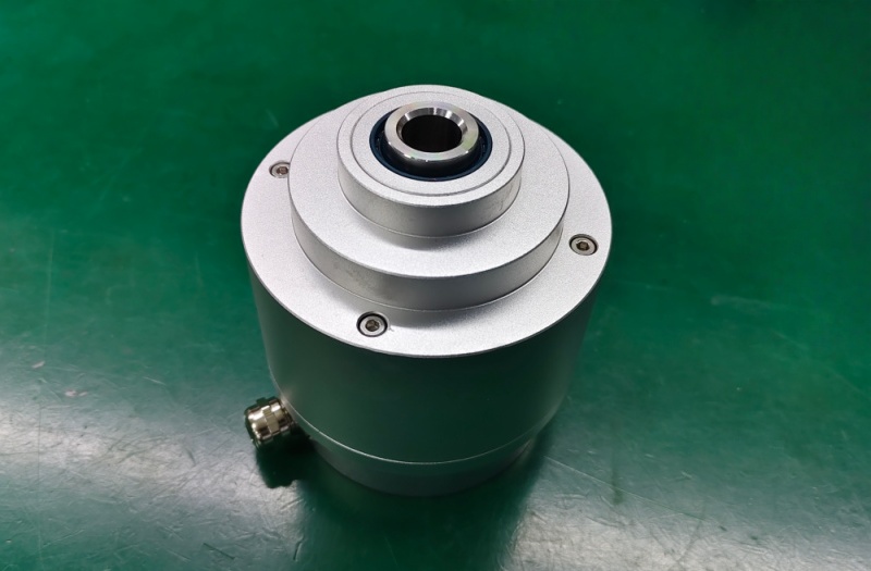
A Profibus encoder is an absolute or incremental rotary encoder that reports position on a Profibus DP fieldbus as a slave device, using a GSD file, a unique station address, and a network-wide baud rate to exchange cyclic process data with a master (PLC or motion controller). Reliable communication depends on matching four things exactly: the GSD file's Ident_Number to the physical device, the station address to what the master's hardware configuration expects, the baud rate across every device on the segment, and the bus termination at both physical ends of the trunk. A mismatch on any one of these does not degrade the signal — the slave either never appears on the bus or drops in and out unpredictably. Common failure patterns include a station reported as "not present" despite correct wiring, a device that communicates at commissioning but fails intermittently in production, position data that reads correctly but preset or parameter commands are silently ignored, and a replacement encoder that is physically installed correctly but never joins the token cycle. This guide covers how Profibus DP encoder communication is established, what GSD and addressing configuration involves, and how each common fault pattern maps back to a specific, checkable cause.
How Profibus DP Encoder Communication Is Established
Profibus DP operates on a master/slave principle with token passing: one or more masters (PLCs, DCS, or Class 2 configuration tools) manage bus traffic, while encoders and other field devices act as slaves that only respond when addressed, never initiating communication on their own. Every device on the segment — master and slave alike — must run at the same baud rate, which can range from 9.6 kbps up to 12 Mbps; the encoder typically auto-detects this rate during startup rather than requiring manual configuration, but every other device sharing the trunk must already be set to that same speed for the segment to function at all.
Before cyclic data exchange begins, the master reads the encoder's GSD (General Station Description) file, a manufacturer-provided text file that declares the device's Ident_Number, supported baud rates, available modules, and I/O data length. On startup, the master compares the Ident_Number reported by the physical encoder against the Ident_Number defined in the imported GSD file; if they don't match — commonly because the GSD file version doesn't correspond to the installed firmware — the master will refuse to bring the slave into data exchange even though the device is powered, wired, and addressed correctly.
Station Addressing and Network Topology
Each Profibus DP slave requires a unique station address in the range of 0 to 125, most often set via rotary or DIP switches directly on the encoder housing. Address 0 is conventionally reserved for the master or a diagnostic tool, and two devices sharing the same address will produce unpredictable bus behavior rather than a clean error on either unit — this makes address conflicts one of the first things to rule out when a newly added or replaced device won't join the network cleanly.
A single Profibus DP segment supports a maximum of 32 stations without repeaters, and up to 126 total across a full network when repeaters are used to link multiple segments, with each repeater itself counting as one station. The bus is a linear trunk using shielded twisted-pair cable with a nominal 150 Ω characteristic impedance, and both physical ends of the trunk require termination — typically a resistor network built into the connector's termination switch — to prevent signal reflections. An unterminated or double-terminated bus produces communication errors that scale with baud rate: the effect can be minor at low speeds and severe at high ones, which is why a segment that worked fine during a slow-speed bench test can fail once commissioned at full production baud rate. Stub or spur lines off the main trunk are not permitted at higher baud rates — at 12 Mbit/s, even a short branch of roughly 30 cm can introduce enough reflection to disrupt communication, so every device must connect directly to the trunk or through the connector's built-in pass-through wiring.
Encoder Profile Class and Parameter Access
Profibus rotary encoders follow a standardized device profile defined in two classes. Class 1 encoders provide position data only and cannot be parameterized over the bus — resolution, direction, and similar settings are fixed at the device. Class 2 encoders support full parameterization, meaning resolution, counting direction, preset value, and software limit switches can be written from the master during configuration or at runtime. The device class also determines the length of the cyclic input/output data block, which is one reason a telegram or module configuration copied from a different class of encoder will produce a length mismatch error rather than simply working with reduced functionality. An encoder that reports position correctly but ignores preset or parameter-write commands is frequently a Class 1 device being treated as Class 2 in the master's configuration, not a bus fault.
Common Profibus Encoder Faults and What Causes Them
Across installed Profibus DP encoder links, the recurring fault pattern is narrow: station reported as not present, intermittent dropouts under production load, parameter or preset commands silently ignored, unexplained bus-wide errors after adding one new device, and a replacement encoder that won't join the token cycle — and each of these maps to a specific, checkable cause rather than a random field fault.
Station reported as "not present" despite correct wiring: check, in order, cable continuity, termination present and correct at both physical ends of the trunk (not doubled up, not missing), the encoder's configured baud rate against the network's actual baud rate, and that the station address is unique on the segment.
Device communicates during commissioning, then drops intermittently once in production: often a termination or stub-line issue that only manifests at the full production baud rate, since low-speed bench testing can mask reflection problems that only appear once the segment runs at its rated speed — high cycle times can also result from DP-V1 acyclic traffic or a Class 2 configuration tool connected during production consuming token-holding time that would otherwise go to cyclic exchange.
Position data present but preset or parameter-write commands have no effect: usually a device-class mismatch — confirm the encoder is genuinely Class 2 and that the master's configuration is treating it as such, rather than assuming parameterization support based on the model family alone.
Adding one new device disrupts communication for devices already on the segment: almost always a station-address collision or a segment that has exceeded 32 stations without a repeater being added, since both faults tend to surface only once a specific device count or address combination is reached rather than at every startup.
GSD import succeeds but the master reports a configuration or module mismatch: the GSD file's Ident_Number doesn't match what the physical device reports, typically because the GSD version doesn't correspond to the installed firmware revision — reconfirm the GSD file against the encoder's actual firmware before assuming a wiring fault.
Replacement encoder is wired and addressed but never enters data exchange: check the Ident_Number match between the GSD file and the physical device first, then baud rate, then station address — these three are the most common blockers and, individually, each one is sufficient to keep a correctly wired device off the bus.
Profibus Gateway and Protocol Conversion
Where an existing Profibus DP master needs to read a device that natively speaks a different protocol — or where an encoder needs to be integrated into a Profibus DP network alongside legacy or mixed-protocol equipment — a Profibus DP gateway can sit between the two, translating cyclic data into the addressing and telegram structure the Profibus master expects. From the master's perspective, the gateway itself appears as a standard GSD-configured slave with its own station address; the complexity of the underlying protocol conversion is hidden behind that single slave definition, but the gateway's own GSD file and Ident_Number still have to be correctly matched during configuration exactly as they would for a native Profibus encoder.
Selecting a Profibus Encoder Replacement
When an installed Profibus DP encoder needs to be matched or replaced, the parameters that must be preserved — in order of how often they cause post-installation failures if missed — are: the GSD file and its Ident_Number, the encoder profile class (1 or 2) and the parameter set it exposes, the station address convention already in use on the segment, and the cyclic data length the master's project expects. Mechanical shaft, flange, and connector interface matter for installation but rarely cause the kind of silent bus failure that an Ident_Number mismatch or class error produces. Confirming these parameters against the original device's configuration before specifying a replacement avoids the majority of post-installation commissioning delays.
For installed Profibus DP encoders that are obsolete, discontinued, or otherwise unavailable from the original source, a custom compatible replacement can be engineered around the confirmed GSD structure, addressing scheme, and mechanical interface of the original unit, preserving the existing PLC project configuration without requiring a full re-commissioning of the bus network.