We developed a custom solution for model OCD-PPA1B-1210-B14S-CRW. Selected when multi-turn absolute feedback is required via parallel push-pull output, using a 58 mm blind hollow structure with 14 mm shaft, without changing an existing parallel-control architecture. Typical production lead time: 15 working days. The referenced configuration is a multi-turn absolute version with optical sensing, 10-bit single-turn resolution, 12-bit multi-turn resolution, binary code, and a mechanical gear-based multi-turn system without battery.
Key Specifications
- Interface: parallel push-pull
- Resolution: 10-bit single-turn + 12-bit multi-turn
- Code: binary
- Multi-turn: mechanical gear train, no battery
- Supply: 10–30 VDC
- Protection: IP66/IP67
- Structure: 58 mm blind hollow, 14 mm shaft, 30 mm depth
- Speed: up to 3000 rpm
Decision Snapshot
- Best for: parallel absolute retrofit systems needing multi-turn position retention
- Key fit: 14 mm hollow shaft, 58 mm blind hollow flange, 30 mm insertion depth
- Avoid if: the system is already built around fieldbus communication or only needs incremental feedback; that is an engineering fit judgment based on the listed parallel interface and direct bit output structure.
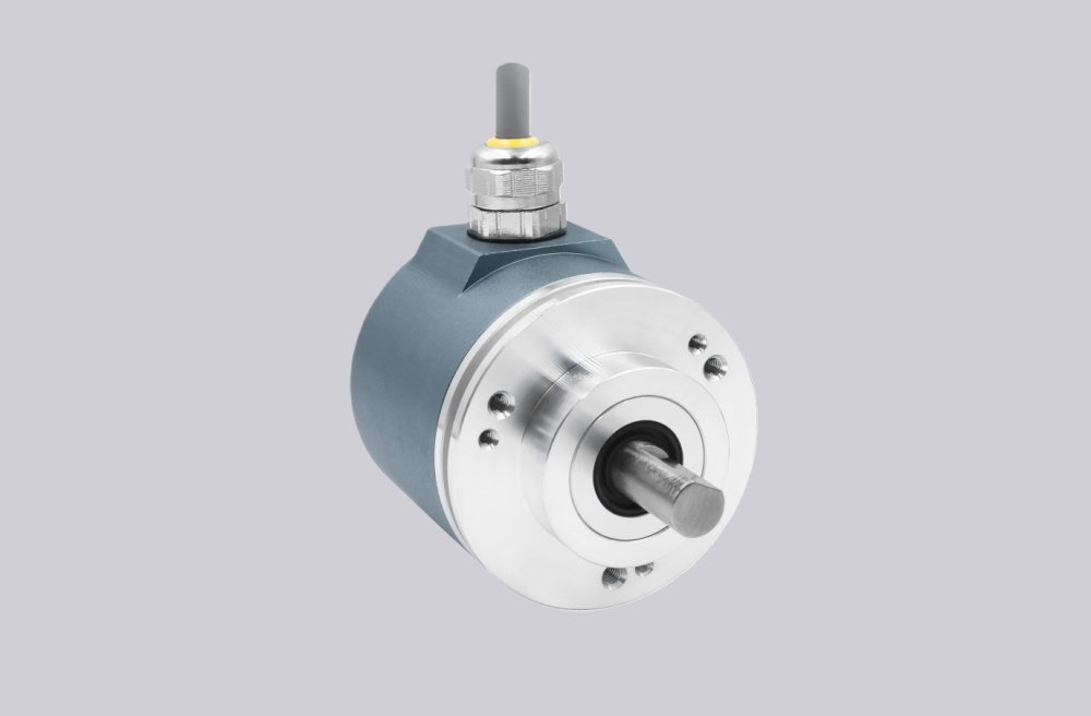
Custom Solution Photos


Encoder structure reference: 58 mm blind hollow flange, 14 mm shaft, radial cable outlet.
Signal & Output Logic
- Bit 1–22 parallel output
- Includes Latch and DIR control
- Direction configurable via cable or connector setting
Primary integration reason: the controller reads direct absolute bit data rather than bus telegrams.
Primary limitation: this architecture is efficient for retrofit, but it is not the right structure for Profibus, CANopen, EtherCAT, or incremental-only systems. That conclusion is based on the published push-pull parallel output and full bit-mapped connection plan.
Wiring & Installation
- Connection: 1 m radial PVC cable
- Cable: AWG 26, 7.1 mm diameter
- Minimum bend radius: 46 mm fixed, 61 mm flexing
Primary commissioning risk: incorrect controller-side bit mapping, especially on higher bit-count parallel systems.
Best practice: verify bit order, latch timing, DIR logic, and common reference before startup. On the mechanical side, blind hollow fit should be checked for insertion depth and alignment, not shaft diameter alone. That installation judgment is supported by the listed 30 mm depth and the published static/dynamic misalignment limits.
Integration & Compatibility
- Designed for parallel absolute encoder systems
- Matches 58 mm blind hollow installation with 14 mm shaft
- Suitable for multi-turn position feedback without battery replacement
- Not suitable for bus-based control structures or simple incremental feedback use cases; this is an engineering selection conclusion from the published interface and output type.
Lead Time
Typical production lead time: 15 working days. Custom adaptation can be developed around shaft fit, cable length, signal assignment, and installation requirements.
Key Technical Data
| Item | Data |
|---|---|
| Model | OCD-PPA1B-1210-B14S-CRW |
| Interface | Parallel push-pull |
| Type | Absolute multi-turn |
| Sensing | Optical |
| Resolution | 10 bit + 12 bit |
| Code | Binary |
| Multi-turn | Mechanical gear train |
| Supply | 10–30 VDC |
| Protection | IP66/IP67 |
| Flange | 58 mm blind hollow |
| Shaft | 14 mm |
| Depth | 30 mm |
| Cable | 1 m radial |
| Speed | 3000 rpm |