We developed a custom solution for model OCD-PPA1G-00AA-B15S-AAW. Selected when single-turn absolute feedback is required via parallel push-pull output, using a 58 mm blind hollow structure with 15 mm shaft, without introducing fieldbus complexity or multi-turn structures. Typical production lead time: 15 working days.
Key Specifications
- Interface: parallel push-pull
- Type: absolute single-turn
- Resolution: 12-bit (typical configuration class)
- Code: Gray
- Supply: 10–30 VDC
- Protection: IP66/IP67
- Structure: 58 mm blind hollow, 15 mm shaft, 30 mm depth
- Connection: axial cable (industrial wiring)
- Sensing: optical
Decision Snapshot
- Best for: direct absolute position feedback in PLC systems without bus communication
- Key fit: 15 mm hollow shaft + parallel interface for simple controller integration
- Avoid if: the system requires multi-turn retention or network-based communication
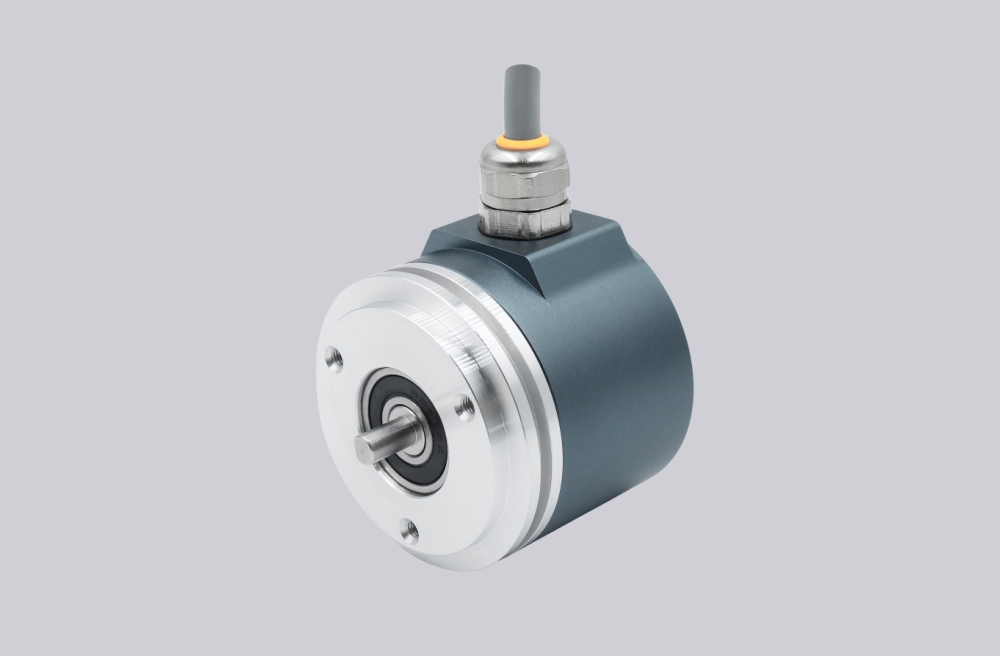
Custom Solution Photos


Encoder structure reference: 58 mm blind hollow flange, 15 mm shaft, axial cable outlet.
Signal & Output Architecture
This model outputs direct parallel bit signals representing absolute position.
Primary engineering value:
No protocol parsing is required — controller reads position directly from hardware-level bit mapping.
Primary system constraint:
Parallel architecture increases wiring complexity and makes the system more sensitive to electrical noise compared to bus-based encoders.
Mechanical & Installation Focus
- Blind hollow shaft structure simplifies mounting on driven shafts
- Compact 58 mm housing for standard installations
Critical engineering insight:
Installation precision directly affects signal quality:
- misalignment → shaft stress + vibration
- vibration → unstable bit transitions
- mechanical tolerance → electrical instability
Unlike bus systems, parallel encoders expose mechanical errors directly as signal issues.
Wiring & EMC Discipline
Parallel output requires strict wiring discipline due to multiple signal lines.
Engineering constraints:
- each signal line must be properly shielded
- grounding must be consistent across all channels
- cable routing must avoid proximity to power lines
- voltage stability must be maintained across all outputs
Key system judgment:
Parallel systems are more affected by EMC than by encoder resolution.
Noise can cause:
- bit flipping
- unstable readings
- incorrect absolute position
Failure Logic & Diagnostics
Typical failure patterns:
- wrong position value → signal interference or wiring mismatch
- unstable reading → shielding or grounding issue
- no output → supply or cable failure
Engineering conclusion:
Most faults originate from wiring complexity, not from encoder sensing.
Integration & Compatibility
- Designed for parallel absolute encoder systems
- Suitable for PLC direct input architectures
- Ideal for applications avoiding fieldbus configuration
- Not suitable for distributed network systems
Lead Time
Typical production lead time: 15 working days. Custom adaptation available for shaft interface, cable length, and signal assignment.
Key Technical Data
| Item | Data |
|---|---|
| Model | OCD-PPA1G-00AA-B15S-AAW |
| Interface | Parallel |
| Type | Absolute single-turn |
| Resolution | 12 bit |
| Code | Gray |
| Supply | 10–30 VDC |
| Protection | IP66/IP67 |
| Flange | 58 mm blind hollow |
| Shaft | 15 mm |
| Depth | 30 mm |
| Connection | Axial cable |