We provide a custom compatible solution for the OCD-DPC1B-1413-S12V-H3P encoder, focused on systems where 13-bit / 14-bit absolute feedback must stay stable over Profibus DP, with correct node addressing, bus termination, stainless housing, and solid 12 mm shaft alignment.
Model reading from the product page:
- OCD-DPC1B-1413-S12V-H3P = absolute multiturn encoder
- Profibus DP interface
- DPV0 / DPV1 / DPV2 Class 2 profile
- 13-bit singleturn resolution
- 14-bit multiturn resolution
- Binary code
- Optical sensing
- 10–30 VDC supply
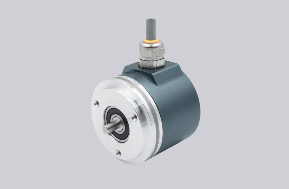
- Synchro flange, Ø58 mm
- Solid Ø12 mm shaft, 20 mm length
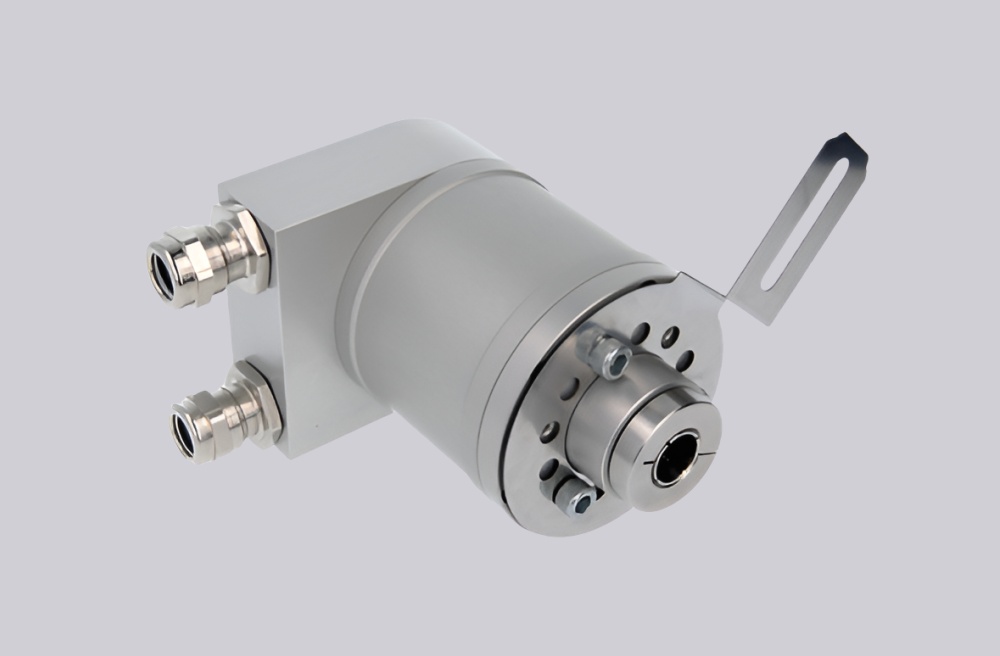
- Stainless steel V2A housing and shaft
- IP66 / IP67 protection
- 3 × cable gland radial connection
Typical production lead time: 15 working days.
This model should be judged as a Profibus feedback node, not just a stainless absolute encoder. The first weak point is usually node number, terminal resistor setting, Bus A / Bus B wiring, cable shielding, or preset/scaling configuration. If the bus layer is wrong, the encoder can be mechanically healthy and still produce unstable or unusable position data.


Where the System Fails First
The product page specifies Profibus DP, transmission rate up to 12 Mbaud, interface cycle time ≥1 ms, and manual functions including address selector switch 0–99 plus terminal resistor with connection cap. These details decide whether the system works in the field. Resolution is not the first problem. Bus topology is.
Typical failure points:
- Wrong node number → PLC cannot identify the encoder
- Incorrect terminal resistor setting → intermittent Profibus faults
- Bus A / Bus B reversed → no stable communication
- Poor shield bonding → telegram errors under inverter noise
- Wrong preset or counting direction → valid data, wrong position
- Rigid coupling or shaft overload → mechanical feedback drift
The connection plan separates Bus in and Bus out lines with power and GND terminals. The removable connection cap makes replacement easier, but it also makes terminal handling critical. If the terminal resistor switch cuts the outgoing bus unexpectedly, the fault may look like a failed encoder while the real problem is bus layout.
Mechanical and Bus Boundary
The stainless V2A construction, Ø12 mm shaft, and IP66/IP67 sealing make this model suitable for harsher industrial locations, but the shaft side still has a hard boundary. The page lists 40 N axial / 110 N radial shaft load, ≤3000 rpm, 10 g vibration, and 100 g shock. If the coupling is rigid or misaligned, bearing load becomes a signal problem before it becomes visible damage.
For this model, the real engineering checkpoint is simple: verify Profibus first, then mechanics. Most site failures start at bus termination, grounding, or node configuration, not at the optical multiturn system.
Installation Notes
- Keep the model format as OCD-DPC1B-1413-S12V-H3P
- Set the Profibus node number before commissioning
- Match terminal resistor setting to the real bus topology
- Wire Bus line A / Bus line B exactly as defined
- Keep cable shield continuous through the connection cap
- Verify preset, scaling, counting direction, and limit-switch settings
- Keep shaft load within 40 N axial / 110 N radial
- Check bus topology before replacing the encoder
Key Data
- Model: OCD-DPC1B-1413-S12V-H3P
- Type: Absolute multiturn encoder
- Interface: Profibus DP
- Profile: DPV0, DPV1, DPV2 Class 2
- Resolution: 13-bit singleturn / 14-bit multiturn
- Code: Binary
- Sensor: Optical
- Supply voltage: 10–30 VDC
- Power consumption: ≤1.5 W
- Transmission rate: ≤12 Mbaud
- Interface cycle time: ≥1 ms
- Flange: Synchro, Ø58 mm
- Shaft: Solid Ø12 mm, 20 mm length
- Housing: Stainless steel V2A
- Connection: 3 × cable gland, radial
- Protection: IP66 / IP67
- Temperature: -40 °C to +85 °C
- Max speed: ≤3000 rpm
- Shaft load: 40 N axial / 110 N radial
- Approval: CE