A custom compatible encoder solution can be provided for UCE-AV002-0413-F100-HFZ in maintenance, retrofit, replacement, and upgrade projects. This model is an analog voltage absolute encoder built on a solid shaft platform with a Ø10 mm shaft, ATEX clamp flange, and hazardous-duty mechanical construction for Zone 1 and 21 oil and gas installations. Typical production lead time: 15 working days. The engineering objective is to preserve the original analog output behavior, shaft-side installation fit, and hazardous-area field continuity so that replacement can remain stable and practical.
Technical Overview of the UCE-AV002-0413-F100-HFZ Encoder
The UCE-AV002-0413-F100-HFZ belongs to an absolute rotary encoder platform using an analog voltage interface. This coded version uses a 13-bit singleturn structure together with a 4-bit multiturn structure, with a default analog code of 0–10 V. The sensor technology is magnetic, and the multiturn function is based on a self-powered magnetic pulse counter without battery using a Wiegand sensor. This makes the model suitable for applications where analog position continuity must be preserved together with a limited multiturn range and battery-free operation.
From the electrical side, the encoder operates on 8–32 VDC, with typical current consumption of 15 mA at 24 V (no load) and startup time under 500 ms. The interface supports start and end point setting via cable or connector, minimum load resistance of 5 kΩ, analog accuracy of ±10 mV at 10 V with ideal power supply, 0.15% linearity, and 32 ms settling time for a full-span step. These characteristics make it suitable for installed analog control systems where scaling, output range, and response behavior must remain aligned with the original application.
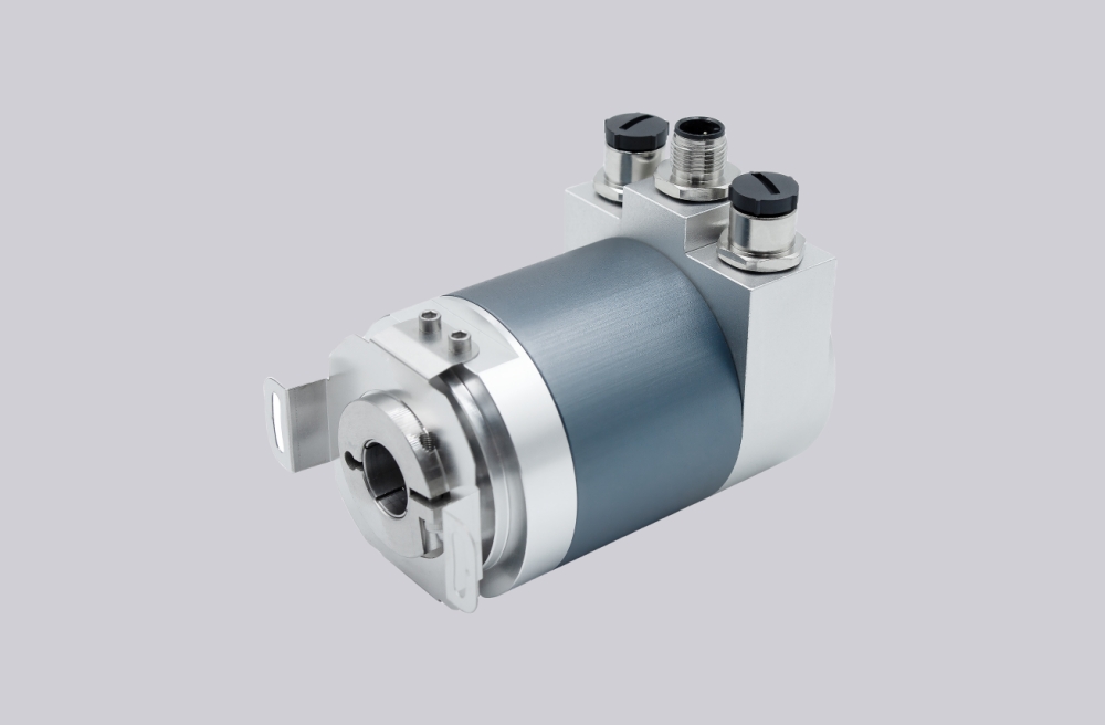
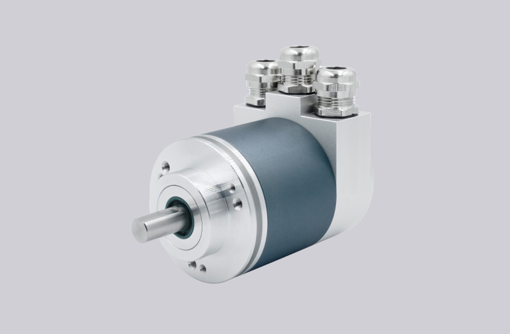
Mechanically, this version uses a solid shaft with single flat, 20 mm shaft length, and Ø10 mm shaft diameter. The flange is a clamp, Ø78 mm, ATEX type, while the housing, flange, and connection cap are all aluminum. The encoder is rated IP65 on the shaft side and IP66/IP67 on the housing side, with operating temperature from -40 °C to +70 °C and maximum permissible mechanical speed up to 3000 rpm.
Industrial Integration Considerations
For this model, the most important compatibility factor is the combination of 0–10 V analog output behavior and programmable start/end point logic. In many retrofit projects, the receiving PLC, analog input card, or display module is already configured around a defined voltage range and measuring span. Replacing the encoder with a mechanically similar unit but different analog scaling, settling behavior, or load requirement can create unnecessary commissioning work. For that reason, the original analog transfer behavior should be preserved together with the shaft and flange dimensions.
The mechanical platform also deserves careful review. This version uses a Ø10 mm solid shaft and a Ø78 mm clamp flange in an ATEX-rated installation concept. In hazardous-duty oil and gas applications, preserving shaft-side fit, flange reference, and enclosure durability is usually as important as maintaining the electrical output range. The hazardous-area approval basis and IP65/IP66/IP67 sealing split between shaft and housing sides should therefore remain aligned with the original installation concept during replacement planning.
Field Installation and Wiring Notes
For this version, the analog start and end point setting should be checked carefully during replacement. The product page specifies manual functions for start and end point via cable or connector, which means the measuring span is part of the original field configuration and should remain consistent during commissioning. The minimum measurement range is listed as 0–11.25°, while the default multiturn range is 16 turns, and scaling can extend measurement up to 32768 turns. These settings should be matched to the original application before startup.
The radial connection arrangement uses 2 x blind plug, radial, so field replacement should also review connection-side sealing integrity, wiring continuity, and original analog input routing. Because this is an analog voltage version, load resistance, supply stability, and noise immunity are especially relevant. In hazardous-duty environments, blind-plug arrangement and cable-entry practice should remain aligned with the installed field configuration.
Custom Compatible Encoder Solution
A custom compatible encoder solution for UCE-AV002-0413-F100-HFZ should preserve five engineering points: Ø10 mm solid shaft geometry, Ø78 mm ATEX clamp flange installation reference, 0–10 V analog output behavior, 13-bit singleturn plus 4-bit multiturn structure, and the original hazardous-duty enclosure concept. This combination matters because successful field replacement depends not only on nominal mounting dimensions, but also on whether the encoder remains aligned with the installed start/end point settings, analog scaling, and multiturn measurement behavior.
From the electrical side, the compatible solution should remain aligned with the original 8–32 VDC supply range, 5 kΩ minimum load resistance, analog accuracy expectations, and settling-time behavior. From the mechanical side, it should preserve shaft dimensions, flange type, aluminum construction, and radial connection layout. Where the original machine already uses custom start/end point settings or extended multiturn scaling, those items should be confirmed during engineering review before final release.
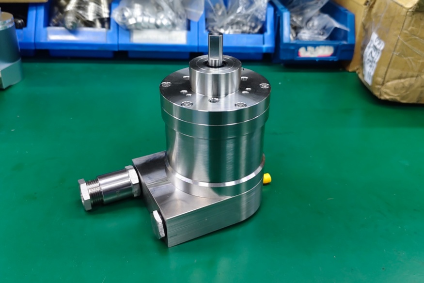
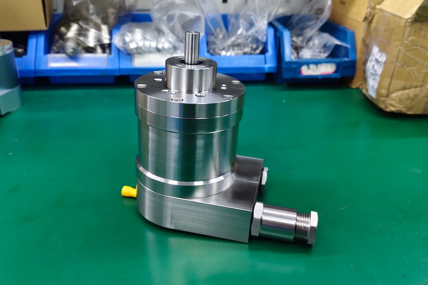
Custom Solution Photos
Lead Time and Custom Development
Typical production lead time: 15 working days.
For custom development, the main checkpoints should include shaft diameter, shaft length, clamp-flange reference, output range, start/end point behavior, minimum load resistance, settling time, and hazardous-area installation continuity. The final coded configuration should be reviewed from both the mechanical and analog-integration sides so that the compatible solution remains aligned with the original field configuration.
Typical Technical Parameters
| Parameter | Specification |
|---|---|
| Encoder Type | Absolute rotary encoder |
| Model | UCE-AV002-0413-F100-HFZ |
| Interface | Analog Voltage |
| Manual Functions | Start and End point via Cable or Connector |
| Supply Voltage | 8 – 32 VDC |
| Current Consumption | Typical 15 mA @ 24 V (no load) |
| Start-Up Time | < 500 ms |
| Min. Load Resistance | 5 kΩ |
| Analog Accuracy | ±10 mV @ 10 V (with ideal power supply) |
| Linearity | 0.15% |
| Settling Time | 32 ms (from min value to max value jump) |
| Reverse Polarity Protection | Yes |
| Short Circuit Protection | Yes |
| Sensing Principle | Magnetic |
| Singleturn Resolution | 13 bit |
| Multiturn Resolution | 4 bit |
| Multiturn Technology | Self Powered Magnetic Pulse Counter (No Battery, Wiegand Sensor) |
| Accuracy (INL) | ±0.0878° (≤ 12 bit) |
| Sense Signal (Default) | Counterclockwise shaft movement (front view on shaft) |
| Code Type | Analog Voltage 0 – 10 V |
| Minimum Measurement Range | 0 – 11.25° |
| Resolution of Output | Max. 13 bits over entire measuring range |
| Multiturn Range | 16 turn default, scalable up to 32768 turns |
| Shaft Type | Solid, Single Flat |
| Shaft Length | 20 mm |
| Shaft Diameter | Ø10 mm |
| Flange Type | Clamp, Ø78 mm, ATEX |
| Max. Shaft Load | Axial 60 N, Radial 80 N |
| Rotor Inertia | ≤ 35 gcm² |
| Friction Torque | ≤ 3 Ncm @ 20 °C |
| Max. Speed | ≤ 3000 rpm |
| Protection Rating | Shaft IP65 / Housing IP66/IP67 |
| Operating Temperature | -40 °C to +70 °C |
| Humidity | 98% RH, no condensation |
| Connection Orientation | Radial |
| Connection Type | 2 x Blind Plug, Radial |
| Connection Cap Material | Aluminium |
| Housing Material | Aluminum |
| Housing Coating | Eloxide |
| Flange Material | Aluminum |
| Weight | 900 g |
| Shock Resistance | ≤ 100 g |
| Vibration Resistance | ≤ 10 g |
| Approval | CE + ATEX Zone 1 & 21 (Oil+Gas) |