A custom compatible encoder solution can be provided for UCE-AV001-0013-E14W-2RW in maintenance, retrofit, replacement, and upgrade projects. This model is built around an analog absolute encoder platform with a blind hollow shaft structure, a Ø14 mm shaft interface, and a stainless-steel Zone 1 & 21 housing intended for oil and gas duty. Typical production lead time: 15 working days. The engineering goal is to preserve the original 0–5 V output behavior, shaft-side fit, hazardous-area installation continuity, and field wiring arrangement so that site replacement work remains practical and controlled.
Technical Overview of the UCE-AV001-0013-E14W-2RW Encoder
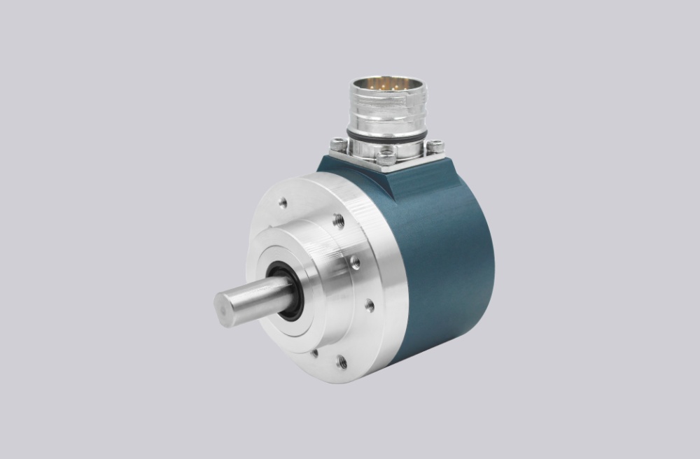
The UCE-AV001-0013-E14W-2RW is an absolute encoder with an analog voltage interface and manual setting capability for the start point and end point through cable or connector. The sensing principle is magnetic, the singleturn resolution is 13 bit, and the multiturn resolution is 0 bit, so this version is a singleturn configuration. The output code is analog voltage 0–5 V, and the default sensing direction is that the value decreases during counterclockwise rotation when viewed from the shaft side.
From the electrical side, the encoder operates on 8–32 VDC, with typical current consumption of 15 mA at 24 V under no load. The minimum load resistance is 5 kΩ, startup time is under 500 ms, analog accuracy at 10 V is ±10 mV under normal supply conditions, linearity is 0.15%, and settling time is 32 ms for a jump from minimum to maximum value. The unit also includes reverse polarity protection and short-circuit protection.
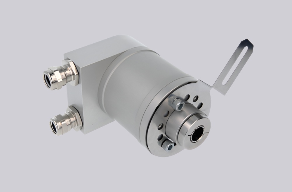
Mechanically, this version uses a blind hollow shaft with 30 mm depth and a shaft diameter of Ø14 mm. The flange form is a Ø78 mm ATEX blind hollow style, the housing and flange materials are stainless steel V4A, and the housing finish is uncoated. The electrical connection direction is radial, and the connection format is listed as cable / connector.
Industrial Integration Considerations
For retrofit work, the most important point on this model is the combination of analog signal continuity and hazardous-area installation suitability. The product page identifies it as a Zone 1 & 21 oil and gas encoder with CE and ATEX approval, so replacement planning should preserve not only shaft fit and signal range, but also enclosure integrity, sealing practice, and application-side installation logic associated with hazardous-duty service.
The analog side also deserves careful review. This encoder provides a 0–5 V output and supports manual start-point and end-point setting through cable or connector, which means the replacement solution should preserve the original scaling strategy, direction behavior, and zero-setting practice already used by the control system. Because the default sensing direction is explicitly defined, rotation interpretation should also be checked during engineering review when installation continuity is important.
Environmental and mechanical durability are also relevant. The encoder is rated IP66/IP67 on both shaft and housing sides, with operating temperature from -30 °C fixed and -5 °C flexible up to +70 °C, humidity tolerance up to 98% non-condensing, maximum shaft load of 60 N axial and 80 N radial, maximum speed up to 3000 rpm, shock resistance up to 100 g, and vibration resistance up to 10 g. These characteristics support use in sealed industrial feedback systems where environmental tolerance and mechanical stability need to remain consistent after replacement.
Custom Compatible Encoder Solution
A custom compatible encoder solution for UCE-AV001-0013-E14W-2RW should focus on five key engineering points: Ø14 mm blind hollow shaft fit, 0–5 V analog output continuity, singleturn 13-bit measurement structure, hazardous-area installation suitability, and preserved field-setting logic for start point, end point, direction, and zero behavior. This matters because successful replacement depends not only on nominal dimensions, but also on whether the encoder remains aligned with the original measurement range strategy and site installation method.
From the mechanical side, the compatible solution should remain consistent with the Ø78 mm ATEX blind hollow flange, 30 mm shaft depth, radial connection direction, and stainless-steel housing platform. From the electrical side, it should preserve the 8–32 VDC supply range, analog output format, and the existing field wiring logic shown by the connection plan, including power supply, ground, analog output, Set1/Direction, Set2/Zero Set, and shielding. These points should be confirmed during engineering review so the final configuration remains matched to the installed application.
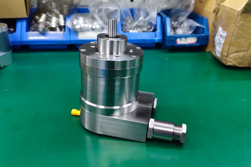
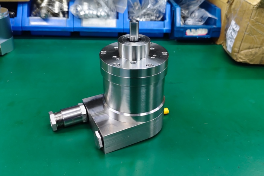
Custom Solution Photos
Lead Time and Custom Development
Typical production lead time: 15 working days.
For custom development, the main checkpoints should include shaft diameter, blind hollow depth, analog output range, start and end point setting logic, radial cable exit, hazardous-area installation requirements, and the original machine-side scaling expectations. Since this model supports manual setting through cable or connector and uses a singleturn magnetic absolute sensing structure, the final coded configuration should be reviewed from both the mechanical and application-signal sides before release.
Typical Technical Parameters
| Parameter | Specification |
|---|---|
| Encoder Type | Absolute encoder, singleturn |
| Model | UCE-AV001-0013-E14W-2RW |
| Interface | Analog Voltage |
| Output Code | 0–5 V |
| Manual Functions | Start and end point can be set via cable or connector |
| Supply Voltage | 8–32 VDC |
| Current Consumption | Typical 15 mA @ 24 V (no load) |
| Start-Up Time | < 500 ms |
| Min. Load Resistance | 5 kΩ |
| Analog Accuracy | ±10 mV @ 10 V |
| Linearity | 0.15% |
| Settling Time | 32 ms |
| Sensing Principle | Magnetic |
| Resolution Singleturn | 13 bit |
| Resolution Multiturn | 0 bit |
| Measurement Range | Singleturn |
| Sense Signal Default | Value decreases during counterclockwise shaft rotation, front view on shaft |
| Shaft Type | Blind hollow, depth 30 mm |
| Shaft Diameter | Ø14 mm |
| Flange Type | Blind Hollow, Ø78 mm ATEX |
| Connection Direction | Radial |
| Connection Type | Cable / connector |
| Protection Rating | IP66 / IP67 |
| Operating Temperature | -30 °C fixed, -5 °C flexible to +70 °C |
| Humidity | 98% RH, no condensation |
| Max. Shaft Load | 60 N axial / 80 N radial |
| Max. Speed | ≤ 3000 1/min |
| Shock Resistance | ≤ 100 g |
| Vibration Resistance | ≤ 10 g |
| Approval | CE + ATEX Zone 1 & 21 (Oil+Gas) |
| Housing Material | Stainless Steel V4A |
| Flange Material | Stainless Steel V4A |