We developed a custom solution for the UCE-AC005-0013-F10W-5RW encoder, intended for hazardous-area systems where 4–20 mA analog position feedback must remain stable under vibration, moisture, industrial noise, and Zone 1 / 21 oil-and-gas installation requirements. This configuration uses a solid Ø10 mm shaft, Ø78 mm ATEX clamp flange, stainless steel V4A housing, magnetic sensing, and a current analog interface. It is not a fieldbus encoder. It is an analog absolute feedback solution where loop load, scaling setup, shielding, and hazardous-area installation quality determine whether the output remains usable. Typical production lead time: 15 working days.
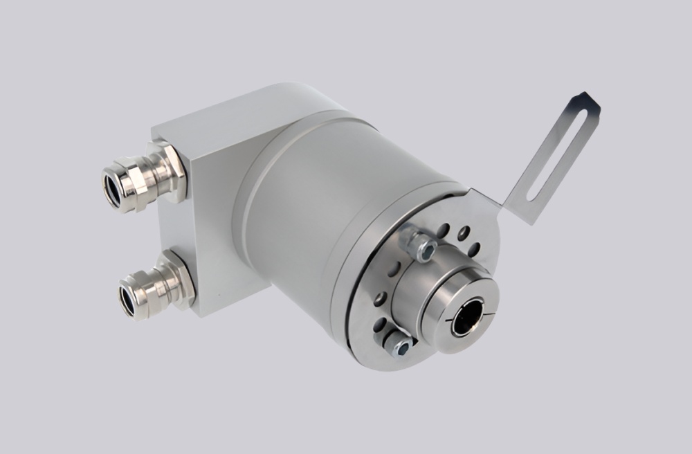
Custom Solution Photos
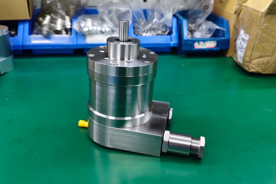
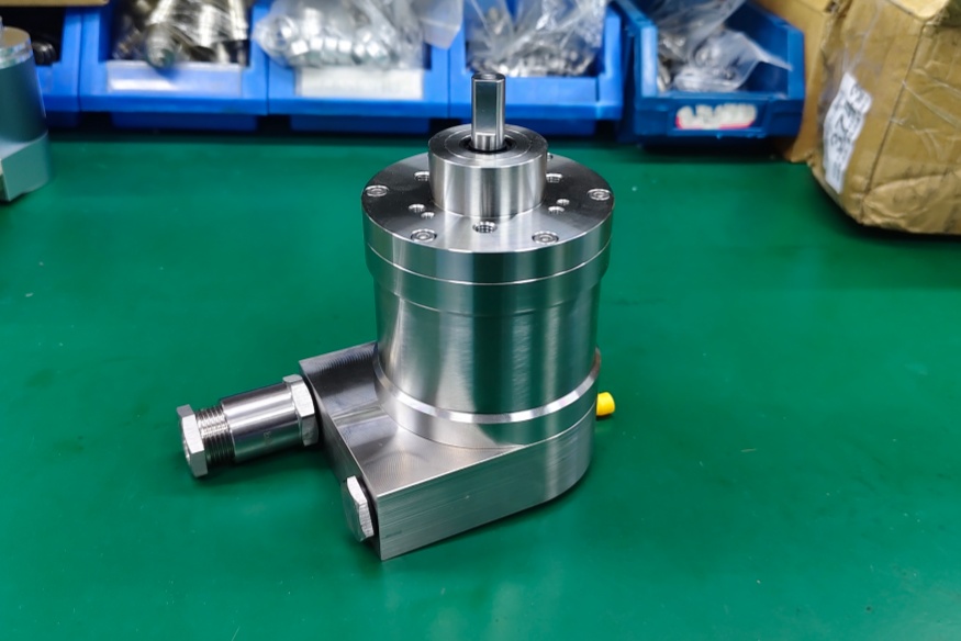
Stable operation depends on clamp mounting quality, cable routing, stainless enclosure integrity, and correct 4–20 mA scaling.
System Limits
- Excess loop resistance → current output accuracy degrades
- Wrong Set1 / Set2 configuration → measuring range or zero point becomes incorrect
- Poor shielding → unstable analog feedback at PLC input
This model uses 4–20 mA analog current output, not SSI, CANopen, Profibus, PROFINET, or parallel logic. The main system bottleneck is analog loop quality and range setting. It provides 13-bit singleturn sensing with a programmable measuring range through cable or connector. If the analog input, grounding, shielding, or set-point logic is wrong, the PLC may receive an incorrect position value even when the encoder is mechanically normal.
Installation and Wiring Constraints
- Wire Power Supply / GND / Analog Output / Set1-Direction / Set2-Zero Set / Shielding correctly
- Match loop resistance to the allowed current-output load range
- Use shielding carefully because analog current feedback can still be affected by EMC and grounding errors
- Respect cable bend radius and protect the radial cable from mechanical stress
- Maintain sealing for CE + ATEX Zone 1 & 21 Oil+Gas service
- Do not exceed the allowed shaft load for the Ø10 mm solid shaft installation
Failure boundary:
- Wrong range setting → incorrect 4–20 mA scaling
- Loop load mismatch → output deviation
- Poor shielding or grounding → unstable PLC value
- Excess shaft load → reduced mechanical reliability
Replacement and Interface Mapping
- Suitable for analog current absolute position feedback systems
- Applicable where 4–20 mA output, ATEX Zone 1 / 21 approval, and stainless housing are required
- Not suitable where digital fieldbus, SSI, CANopen, or parallel output is expected
- Best used where PLC analog input quality, loop load, shielding, and range setup can be controlled
Key Data
- Model: UCE-AC005-0013-F10W-5RW
- Type: Absolute encoder, analog current
- Interface: 4–20 mA analog output
- Sensor technology: Magnetic
- Singleturn resolution: 13 bit
- Multiturn: 0 bit / singleturn
- Supply voltage: 8–32 VDC
- Start-up time: <500 ms
- Output scaling: programmable by Set1 / Set2
- Flange: Clamp flange, Ø78 mm ATEX
- Shaft: Solid Ø10 mm, single flat, length 20 mm
- Housing: Stainless steel V4A / 316L
- Protection: IP66 / IP67
- Approval: CE + ATEX Zone 1 & 21 Oil+Gas