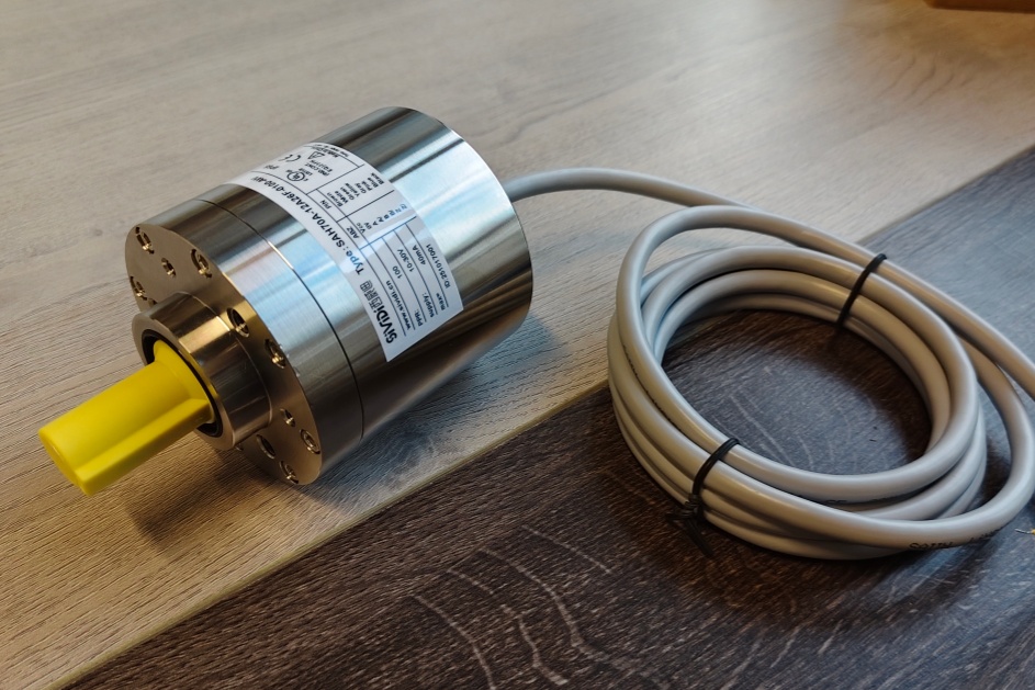


We provide a custom compatible solution for the 110-03075 encoder, focused on systems where 512 × 512 absolute feedback must remain stable over ASI RS485 wiring, with correct DATA+/DATA- polarity, shield continuity, 2 ms response timing, and CCW counting direction.
Model reading from the document:
- 110-03075 = absolute rotary encoder
- 512 steps per revolution
- 512 revolutions
- ASI RS485 interface
- Binary code
- 11–27 VDC supply
- RS485 output level
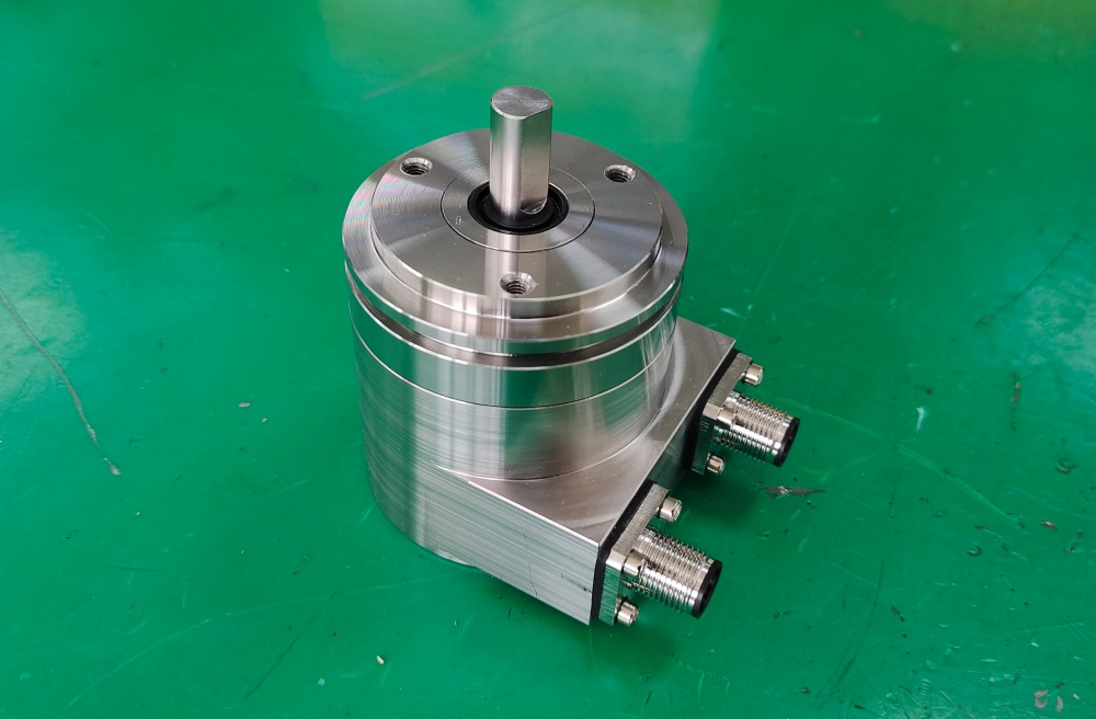
- ZB36 flange
- 10FL / 19.5 shaft
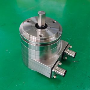
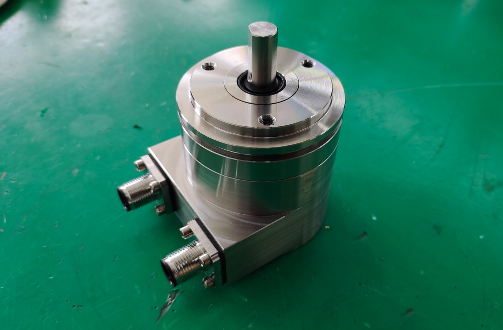
- 2 × 5-pole connector structure
- IP65 protection
- 0–60 °C operating temperature
- Response time: 2 ms
- Counting direction: CCW
Typical production lead time: 15 working days.
This model should be handled as a low-resolution absolute RS485 feedback node, not as SSI, Profibus, PROFINET, CANopen, analog, or incremental output. The first weak point is usually DATA+/DATA- polarity, shielding, bus-cap protection, supply stability, or controller response-time expectation.
Where the System Fails First
The signal structure is simple: Supply Voltage / DATA- / Ground / DATA+ / Screen. That simplicity makes wiring errors easy to miss. If DATA+ and DATA- are reversed, or if the shield is not bonded correctly, the controller may show intermittent communication or no usable position value.
Typical failure points:
- DATA+ / DATA- reversed → no stable RS485 data
- Poor screen connection → noisy communication
- Wrong counting direction assumption → reversed position logic
- Controller not matching 2 ms response behavior → unstable reading
- Weak supply or shared ground noise → intermittent output
- Connector-side strain → long-term communication fault
The drawing also shows the shielding point and two radial 5-pole connector positions. In this structure, connector quality and shield bonding are not secondary details. They are usually where the field problem starts before the encoder body itself fails.
Mechanical and Signal Boundary
Mechanically, the encoder uses a ZB36 flange and 10 mm flat shaft, 19.5 mm length. Shaft load is not the main system story here. The more important boundary is the ASI RS485 communication layer and whether the controller expects the same binary format, CCW direction, and 2 ms response time.
The document also lists bus cap with Transil BZW04P13B, which means surge/transient protection is part of the interface behavior. If the replacement wiring ignores shielding or transient exposure, communication faults may appear even when the encoder parameters match.
Installation Notes
- Keep the model format as 110-03075
- Match the newer reference 0002-13075 where required
- Wire DATA+ / DATA- exactly as defined
- Keep the Screen connection continuous
- Confirm CCW counting direction before production startup
- Verify the controller can work with 2 ms response time
- Keep supply voltage within 11–27 VDC
- Check connector strain and shield bonding before replacing the encoder
Key Data
- Model: 110-03075
- New reference: 0002-13075
- Type: Absolute rotary encoder
- Interface: ASI RS485
- Code: Binary
- Resolution: 512 steps / revolution
- Multiturn range: 512 revolutions
- Supply voltage: 11–27 VDC
- Output level: RS485
- Flange: ZB36
- Shaft: 10FL / 19.5
- Connector: 2 × 5-pole
- Protection: IP65
- Operating temperature: 0–60 °C
- Counting direction: CCW
- Response time: 2 ms
- Pinout: ST2518
- MTTFd: ≥100 years
- Drawing: 04-418-3170