A tailored compatible encoder solution can be developed for OCM-DPC1B-1212-F10W-HFZ in maintenance, retrofit, replacement, and upgrade applications. This type of configuration is typically used where the original machine architecture depends on Profibus DP position feedback, multiturn absolute continuity, and a heavy-duty shaft-mounted installation suitable for hazardous-duty environments. Typical production lead time: 15 working days. During engineering review, the main compatibility points usually include Profibus communication behavior, node setting method, terminal resistor continuity, shaft and flange fit, radial connection arrangement, and enclosure sealing performance.
Technical Overview of the OCM-DPC1B-1212-F10W-HFZ Encoder
The OCM-DPC1B-1212-F10W-HFZ is an optical absolute encoder built around a Profibus DP interface with support for DPV0, DPV1, and DPV2 Class 2 communication profiles. Its resolution structure is 12 bit singleturn combined with 12 bit multiturn, using binary code and mechanical gearing for turn counting without battery dependence. This combination makes the model suitable for systems that require retained absolute position information across multi-turn motion ranges while maintaining fieldbus-based integration with PLC or drive-level control architectures.
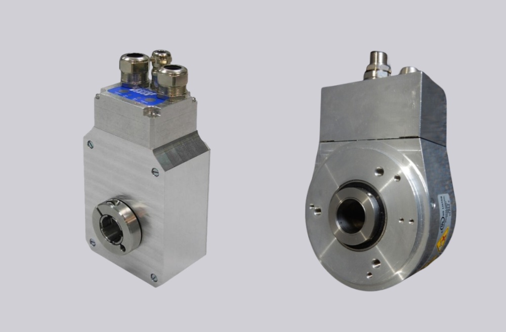
Mechanically, this version uses a solid shaft with single flat, 10 mm shaft diameter, 20 mm shaft length, and a 78 mm clamp flange construction. The housing and flange are stainless steel, while the connection side uses a radial dual blind-plug arrangement. In practical replacement work, this means the engineering focus is not limited to protocol matching. Shaft geometry, clamping continuity, service access around the radial cable side, and sealing preservation are all part of the actual compatibility requirement.
A further defining feature is its bus-oriented field configuration logic. The published interface data includes address selector switch 0–99 and terminal resistor handling through the connection cap, along with programmable functions such as resolution, gearing factor, velocity scaling and filter, preset, counting direction, limit switches, node number, teach-in, and diagnosis. This indicates that a compatible solution must be reviewed as a communication-integrated feedback device rather than as a simple mechanical encoder body.
Industrial Integration Considerations
In retrofit projects, the first critical checkpoint is Profibus DP network continuity. A compatible replacement should be aligned with the original bus structure, including transmission rate capability up to 12 Mbaud, minimum interface cycle time of 1 ms, galvanically isolated Profibus data interface behavior, and the expected device profile on the master side. Even when the nominal resolution appears straightforward, actual integration can still depend on existing PLC configuration files, bus timing tolerance, node assignment logic, and plant commissioning practice.
The second checkpoint is network-side commissioning continuity. This model is not only an encoder with absolute output, but also a bus node that participates in addressing, diagnostics, and line termination strategy. Where the original installation uses bus in / bus out daisy-chain topology, replacement work should preserve the continuity of incoming and outgoing A/B lines, power feed structure, and resistor setting method. This is especially important in cabinets or field installations where maintenance access is limited and any change to bus structure may affect downstream devices.
The third checkpoint is environmental and mechanical duty continuity. The published construction includes stainless steel housing materials, IP66/IP67 protection, -40 °C to +70 °C operating range, and ATEX Zone 1 & 21 approval. For this reason, engineering review should confirm not only the communication layer, but also the shaft loading condition, enclosure integrity, and suitability for wet, dusty, corrosive, or hazardous-duty locations where mechanical robustness and sealing stability are part of the original system design intent.
Field Installation and Wiring Notes
For field wiring, the most important point is preservation of Profibus line continuity through the radial dual-plug connection structure. The published connection plan shows separate Bus in and Bus out paths for line A and line B, together with duplicated power supply and GND positions. During retrofit, these circuits should be checked conductor by conductor instead of assuming that a mechanical fit automatically guarantees bus continuity. Incorrect A/B line assignment or interruption of the daisy-chain structure can result in network instability that appears as intermittent encoder failure.
Because the model uses address selector switch 0–99 and terminal resistor handling through the connection cap, commissioning personnel should confirm that the node address and line termination state remain consistent with the original field configuration before energizing the network. This is particularly important when the encoder is located at the end of a Profibus segment, since an incorrect resistor setting may disturb the full segment rather than only the local device. In retrofit work, this step often matters more than nominal resolution matching.
Cable routing should also be reviewed carefully. The radial connection layout and blind-plug structure can influence bending radius, gland clearance, and service access around protective covers or machine frames. In hazardous-duty installations, sealing continuity at the connection side must be preserved, and any cable gland or plug arrangement used in the replacement solution should be selected so that the original enclosure protection concept is not weakened during installation or later maintenance.
On the mechanical side, the 10 mm solid shaft with single flat and clamp flange arrangement means shaft fit, clamping force, and alignment condition should be checked before startup. The maximum permissible mechanical speed is 3000 rpm, with axial load up to 60 N and radial load up to 80 N. In practice, shaft misalignment, bracket stress, or excessive coupling preload can shorten service life even when electrical communication is correct, so replacement work should treat mounting geometry as part of the signal reliability chain.
Custom Compatible Encoder Solution
A custom compatible encoder solution for OCM-DPC1B-1212-F10W-HFZ can be engineered around the original fieldbus and installation requirements. The first compatibility target is Profibus DP communication continuity, including profile behavior, node addressing, bus timing, and diagnostic interaction with the control system. The second target is multiturn absolute feedback continuity, so that the existing machine logic can continue to use retained position information without reworking the broader control strategy.
The third target is the mechanical interface, including the 10 mm solid shaft, single-flat shaft format, 20 mm shaft length, and 78 mm clamp flange installation envelope. The fourth target is field wiring continuity, especially where bus in / bus out topology, terminal resistor setting, and radial connection space limitations are already fixed by the machine layout. The fifth target is environmental continuity, including IP66/IP67 sealing, stainless construction expectations, and suitability for hazardous-duty operation. These points should be confirmed during engineering review so that the replacement proposal is matched to the original working configuration rather than to catalog appearance alone.
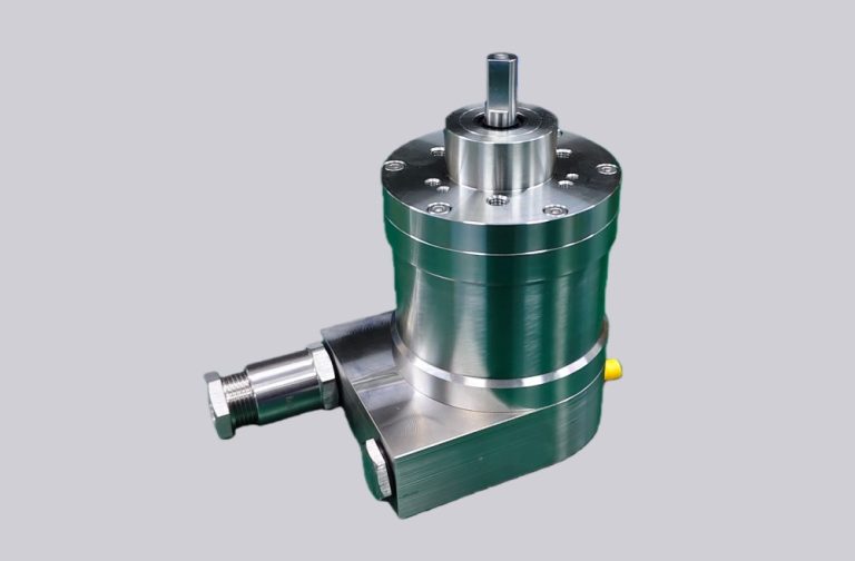
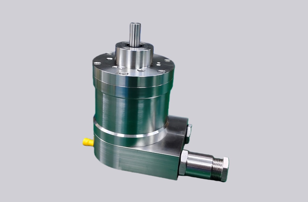
Custom Solution Photos
Lead Time and Custom Development
Typical production lead time: 15 working days.
For projects based on OCM-DPC1B-1212-F10W-HFZ, custom development normally starts with confirmation of the Profibus profile requirement, singleturn and multiturn structure, shaft dimensions, flange installation details, node addressing method, and terminal resistor handling. Where the original field configuration includes specific bus topology, scaling logic, teach-in behavior, or hazardous-duty cable entry arrangement, these items should be checked before production release to reduce retrofit modification work and preserve commissioning continuity.
Typical Technical Parameters
| Parameter | Specification |
|---|---|
| Model | OCM-DPC1B-1212-F10W-HFZ |
| Encoder Type | Absolute encoder |
| Interface | Profibus DP |
| Profile | DPV0, DPV1 and DPV2 Class 2 |
| Transmission Rate | ≤ 12 Mbaud |
| Interface Cycle Time | ≥ 1 ms |
| Manual Functions | Address selector switch 0–99 and terminal resistor (with connection cap) |
| Programming Functions | Resolution, gearing factor, velocity scaling + filter, preset, counting direction, limit switches, node number, teach-in, diagnosis |
| Output Driver | Profibus data interface, galvanically isolated via opto-couplers |
| Supply Voltage | 10 – 30 VDC |
| Current Consumption | ≤ 230 mA @ 10 VDC, ≤ 100 mA @ 24 VDC |
| Power Consumption | ≤ 2.5 W |
| Start-Up Time | < 1 s |
| Sensor Technology | Optical |
| Singleturn Resolution | 12 bit |
| Multiturn Resolution | 12 bit |
| Multiturn Technology | Mechanical gearing, no battery |
| Output Code | Binary |
| Protection Class | IP66/IP67 |
| Operating Temperature | -40 °C to +70 °C |
| Humidity | 98% RH, no condensation |
| Shaft Type | Solid, single flat |
| Shaft Diameter | 10 mm |
| Shaft Length | 20 mm |
| Flange Type | Clamp, ø 78 mm, ATEX |
| Housing Material | Stainless steel V4A (316L) |
| Connection Orientation | Radial |
| Connection Type | 2 × Blind Plug, Radial |
| Max. Shaft Load | Axial 60 N, Radial 80 N |
| Max. Mechanical Speed | ≤ 3000 rpm |
| Shock Resistance | ≤ 100 g |
| Vibration Resistance | ≤ 10 g |
| Approval | CE + ATEX Zone 1 & 21 (Mining) |
| Product Life Cycle | Established |