A custom compatible encoder solution can be provided for OCE-S101B-0412-E14W-HFZ in maintenance, retrofit, replacement, and upgrade projects. This type of solution is typically required where the original field installation uses an SSI absolute feedback structure with preset input, blind hollow shaft mounting, and explosion-protected mechanical construction. Typical production lead time: 15 working days. During engineering review, the key matching points normally include SSI timing continuity, preset logic behavior, hollow shaft fit, radial connection layout, sealing continuity, and hazardous-duty installation requirements.
Technical Overview of the OCE-S101B-0412-E14W-HFZ Encoder
The OCE-S101B-0412-E14W-HFZ is an optical absolute encoder configuration built around an SSI with Preset interface and RS422 signal level. Its resolution structure is 12 bit singleturn with 4 bit multiturn, using binary code and a clockwise counting convention when viewed from the shaft side. The unit is designed with a blind hollow shaft, 14 mm bore diameter, 30 mm shaft depth, and a radial dual blind-plug connection arrangement. This configuration is especially relevant in applications where shaft insertion depth, cable outlet direction, and enclosure integrity must remain aligned with the original field design.
From an integration perspective, the most important feature is not only the resolution itself, but the combination of SSI clock/data transmission, preset capability, and mechanical installation format. The published electrical data shows a 4.5–30 VDC supply range, clock frequency from 100 kHz to 2 MHz, RS422 clock input via optocoupler, and power consumption of no more than 1.5 W. These points matter when preparing a custom compatible replacement because controller timing tolerance, line driver format, and preset activation method need to be kept consistent with the original machine logic.
Industrial Integration Considerations
For retrofit work, the first engineering checkpoint is SSI communication continuity. A replacement design should be matched to the original controller’s clock rate, binary data expectation, direction logic, and preset behavior. Even where the nominal resolution is known, field compatibility can still depend on the controller scan cycle, the allowed interface cycle time, and whether the receiving hardware expects RS422-level differential signals without additional conversion. The original published cycle time is at least 25 µs, and this should be considered during compatibility review for older PLC or motion interfaces.
The second integration checkpoint is hazardous-duty mechanical continuity. This model is built for Zone 1 & 21 service with stainless steel housing parts, IP66/IP67 shaft and housing protection, and a relatively heavy-duty 78 mm ATEX flange construction. In replacement projects, it is therefore not enough to match the signal only. The housing envelope, shaft engagement depth, cable entry sealing path, and environmental protection concept should also be reviewed so that the installed system preserves its original operating reliability in oil, gas, dust, moisture, and washdown-related environments.
A third point is multiturn behavior. Since the published multiturn technology is mechanical gearing without battery support, a compatible solution should be engineered with attention to the same functional expectation for turn counting continuity. This is especially important in machines that perform homing reduction, retained position logic, or long-stroke angular conversion through multiturn feedback.
Field Installation and Wiring Notes
In field wiring, the main concern for this model is correct handling of the differential SSI lines and auxiliary control inputs. The published connection plan identifies GND, power supply, DIR, Preset, Clock+, Clock-, Data-, and Data+ on an 8-position layout. During retrofit, pin continuity should be checked point by point instead of assuming direct conductor equivalence, especially where the original installation uses customized cable cores, terminal transitions, or junction box remapping.
Because the connection orientation is radial and the unit uses two blind plugs, cable routing clearance should be reviewed before installation. This matters in compact machinery where conduit direction, gland spacing, or protective cover interference may affect service access. In hazardous-duty environments, sealing continuity around the connection side must be maintained, and the cable or mating connection hardware should be selected so that enclosure protection is not weakened during replacement work.
For SSI commissioning, shield bonding and signal routing should be handled conservatively. Clock and data pairs should be kept away from power switching lines, and the differential pair integrity should be preserved through the full cable path. The specified clock range of 100 kHz to 2 MHz means long cable runs, noisy inverter cabinets, or mixed grounding practices can influence communication stability if wiring discipline is poor. Direction input and preset input behavior should also be tested during startup so that counting orientation and zero reference logic remain aligned with the original machine configuration.
Mechanical installation should also be checked carefully. The published static and dynamic misalignment allowances are limited, and the maximum permissible mechanical speed is 3000 rpm. For hollow-shaft retrofits, shaft diameter, insertion depth, runout condition, and anti-rotation stability should all be verified before energizing the system. This helps reduce coupling stress, bearing-side loading, and premature sealing wear in continuous-duty operation.
Custom Compatible Encoder Solution
A custom compatible encoder solution for OCE-S101B-0412-E14W-HFZ can be engineered around the original field requirements rather than around nominal catalog similarity alone. The first matching target is the SSI electrical structure, including RS422 differential transmission, clock/data timing range, binary output format, and direction input logic. The second target is preset-function continuity, so that commissioning and position reset behavior remain practical for the existing control system.
The third matching target is the mechanical interface. For this configuration, that normally means preserving the blind hollow shaft format, 14 mm shaft diameter, 30 mm engagement depth, radial connection concept, and the installation envelope associated with the 78 mm flange arrangement. The fourth target is environmental continuity, including enclosure sealing, stainless construction expectations, and suitability for harsh-duty or hazardous-area installation practices. The fifth target is operating continuity under the original temperature, shock, and vibration conditions, so the replacement proposal is reviewed as a working engineering fit rather than as a generic catalog substitute.
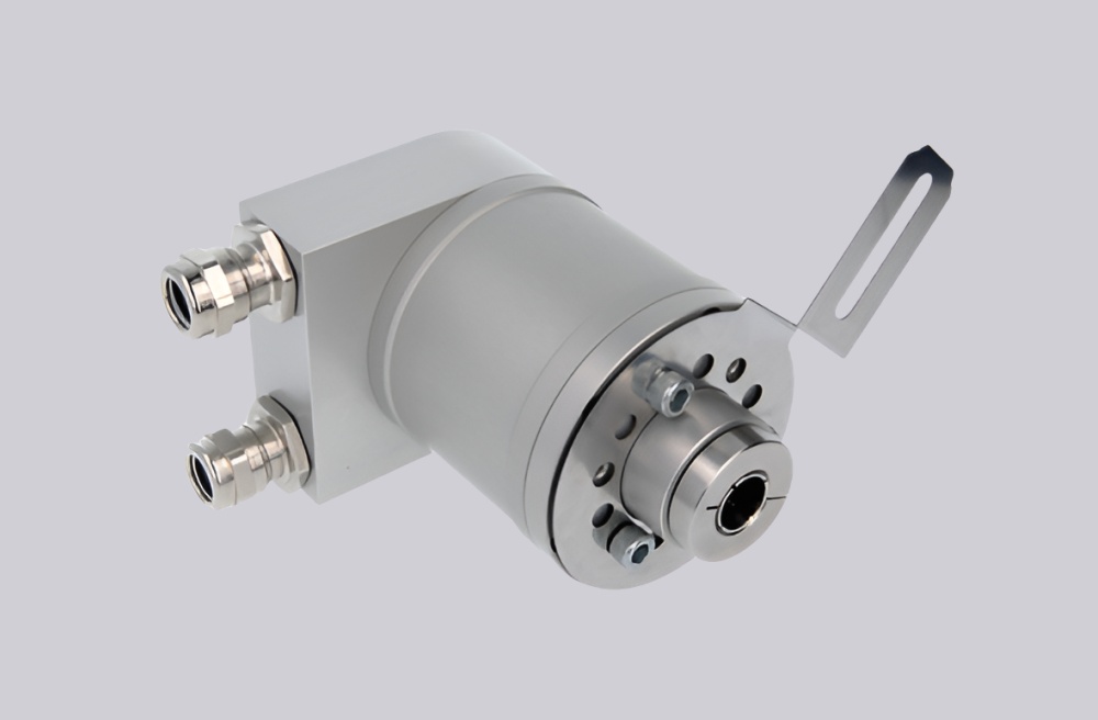
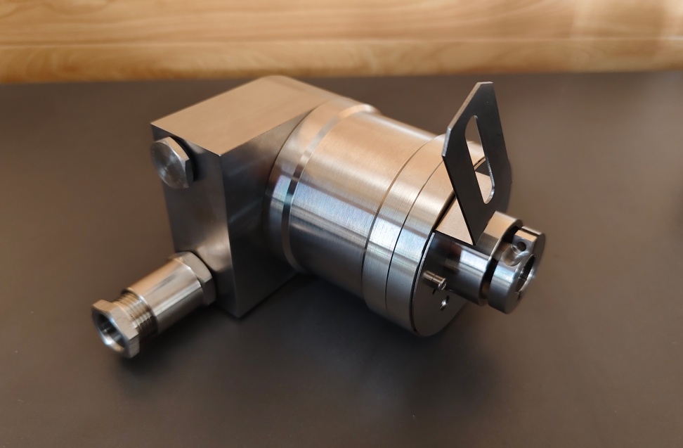
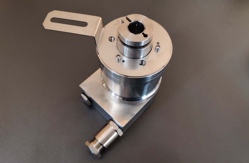
Custom Solution Photos
Lead Time and Custom Development
Typical production lead time: 15 working days.
For projects involving this model, custom development normally begins with confirmation of the original SSI data structure, multiturn requirement, shaft and flange dimensions, connection-side layout, and field installation constraints. Where the original coded version includes application-specific direction logic, preset handling, or hazardous-duty cable entry requirements, these points should be confirmed during engineering review before final production release. This approach is intended to reduce modification work during retrofit and preserve installation continuity in existing equipment.
Typical Technical Parameters
| Parameter | Specification |
|---|---|
| Model | OCE-S101B-0412-E14W-HFZ |
| Encoder Type | Absolute encoder |
| Interface | SSI with Preset |
| Manual Functions | Preset + complement via cable or connector |
| Interface Cycle Time | ≥ 25 µs |
| Output Driver | RS422 |
| Supply Voltage | 4.5 – 30 VDC |
| Power Consumption | ≤ 1.5 W |
| Start-Up Time | < 1 s |
| Clock Input | RS422 via optocoupler |
| Clock Frequency | 100 kHz – 2 MHz |
| Sensing Technology | Optical |
| Singleturn Resolution | 12 bit |
| Multiturn Resolution | 4 bit |
| Multiturn Technology | Mechanical gearing, no battery |
| Output Code | Binary |
| Counting Direction | Clockwise shaft movement (front view on shaft) |
| Accuracy (INL) | ±0.0439° (≤13 bit) |
| Shaft Type | Blind hollow |
| Shaft Diameter | 14 mm |
| Shaft Depth | 30 mm |
| Flange Type | 78 mm blind hollow flange |
| Connection Orientation | Radial |
| Connection Type | 2 × blind plug, radial |
| Protection Class | IP66/IP67 |
| Operating Temperature | -40 °C to +70 °C |
| Housing Material | Stainless steel V4A / 316L |
| Max. Mechanical Speed | ≤ 3000 rpm |
| Max. Shaft Load | Axial 60 N / Radial 80 N |
| Shock Resistance | ≤ 100 g |
| Vibration Resistance | ≤ 10 g |
| Approval | CE + ATEX Zone 1 & 21 |