A custom compatible encoder solution can be provided for OCM-DPC1B-1212-E14W-HFZ in maintenance, retrofit, replacement, and upgrade scenarios. This configuration is typically used in systems relying on Profibus DP communication, multiturn absolute position feedback, and blind hollow shaft mounting in harsh-duty or hazardous environments. Typical production lead time: 15 working days. During engineering review, key matching points include Profibus profile continuity, node addressing method, bus termination handling, shaft fit, and sealing integrity under original operating conditions.
Technical Overview of the OCM-DPC1B-1212-E14W-HFZ Encoder
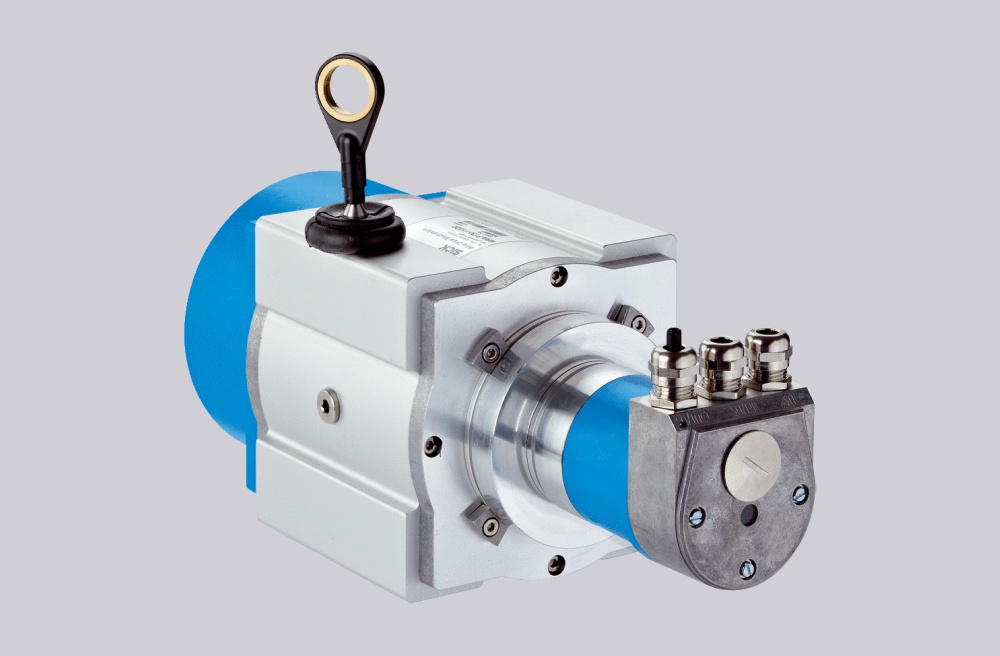
The OCM-DPC1B-1212-E14W-HFZ is an optical absolute encoder with Profibus DP interface supporting DPV0, DPV1, and DPV2 Class 2. It combines 12 bit singleturn and 12 bit multiturn resolution using binary output and mechanical gearing without battery support.
This version features a blind hollow shaft with 14 mm bore and 30 mm depth, paired with a 78 mm flange and radial dual-plug connection layout. The unit is designed for stable integration in fieldbus-based motion systems where both communication and mechanical installation continuity must be preserved.
Industrial Integration Considerations
The primary integration concern is Profibus communication alignment. A compatible solution should match the original controller configuration, including transmission rate (up to 12 Mbaud), cycle time (≥1 ms), node addressing, and diagnostic behavior. Differences in device profile or parameter structure may affect commissioning even when resolution appears identical.
The second consideration is environmental and mechanical continuity. This model is designed for demanding conditions with stainless steel housing, IP66/IP67 protection, and a wide temperature range. Shaft engagement, installation space, and sealing structure should be evaluated to maintain long-term operational reliability.
Field Installation and Wiring Notes
Field wiring should preserve the original Profibus bus structure. The encoder uses a radial dual-plug layout with separate bus in and bus out lines (A/B channels), along with duplicated power supply and ground connections. During replacement, conductor mapping should be verified point by point to avoid communication instability.
Node address settings and terminal resistor configuration must be checked before startup. Incorrect termination, especially at the end of a bus segment, can affect the entire network rather than a single device. In many cases, communication issues originate from wiring or addressing changes rather than encoder failure.
Cable routing around the radial connection should also be reviewed. Limited installation space, bending radius constraints, and sealing requirements may influence cable gland selection and maintenance access. For hazardous-duty installations, enclosure integrity must be preserved during replacement.
Custom Compatible Encoder Solution
A custom compatible encoder solution for OCM-DPC1B-1212-E14W-HFZ typically focuses on:
- Profibus DP communication profile, addressing, and bus timing alignment
- 12 bit singleturn + 12 bit multiturn absolute feedback continuity
- Blind hollow shaft interface (14 mm bore, 30 mm depth)
- Radial dual-plug wiring with bus in / bus out consistency
- IP66/IP67 sealing and harsh-duty installation suitability
These factors should be confirmed during engineering review to ensure compatibility with the original system configuration.
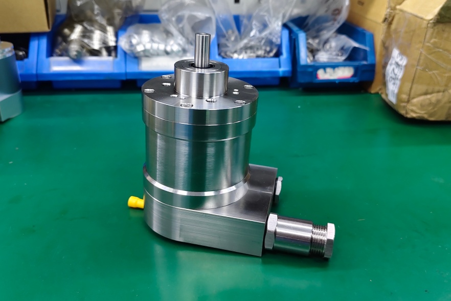
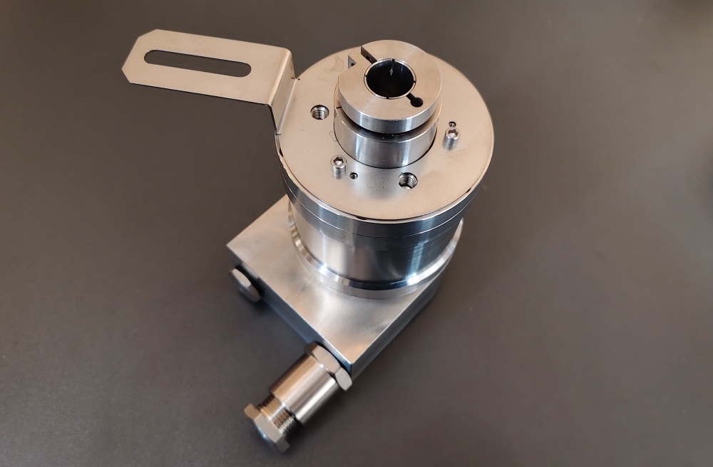
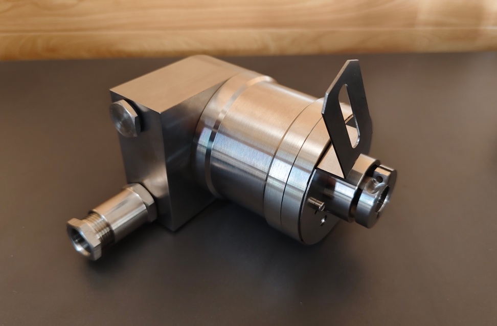
Custom Solution Photos
Lead Time and Custom Development
Typical production lead time: 15 working days.
Custom development typically starts with confirmation of Profibus configuration, shaft dimensions, node addressing, and wiring layout to minimize modification work during retrofit.
Typical Technical Parameters
| Parameter | Specification |
|---|---|
| Model | OCM-DPC1B-1212-E14W-HFZ |
| Encoder Type | Absolute encoder |
| Interface | Profibus DP |
| Profile | DPV0, DPV1 and DPV2 Class 2 |
| Transmission Rate | ≤ 12 Mbaud |
| Interface Cycle Time | ≥ 1 ms |
| Manual Functions | Address selector switch 0–99 and terminal resistor |
| Programming Functions | Resolution, preset, direction, scaling, node setting, diagnosis |
| Supply Voltage | 10 – 30 VDC |
| Power Consumption | ≤ 2.5 W |
| Resolution | 12 bit singleturn + 12 bit multiturn |
| Multiturn Technology | Mechanical gearing, no battery |
| Output Code | Binary |
| Shaft Type | Blind hollow |
| Shaft Diameter | 14 mm |
| Shaft Depth | 30 mm |
| Flange Type | Ø78 mm ATEX flange |
| Connection Type | 2 × Blind Plug, Radial |
| Protection Class | IP66/IP67 |
| Operating Temperature | -40 °C to +70 °C |
| Housing Material | Stainless steel (316L) |
| Max. Shaft Load | Axial 60 N / Radial 80 N |
| Max. Speed | ≤ 3000 rpm |
| Approval | CE + ATEX Zone 1 & 21 |