CEV65S-00169 should be replaced as a Profibus-DP absolute encoder with legacy terminal wiring, not as a generic fieldbus encoder; EncoderWorks can configure a custom compatible replacement solution when the controller must keep the same 8192-step position range, PNO Class 2 profile behavior, RS485 bus level, node address method, 3×PG9 radial wiring, ZB80 flange, and 10FL/24 shaft interface. The main failure boundary is a replacement that communicates on Profibus but changes address setting, bus termination, preset wiring, or mechanical fit. Typical production lead time: 15 working days.
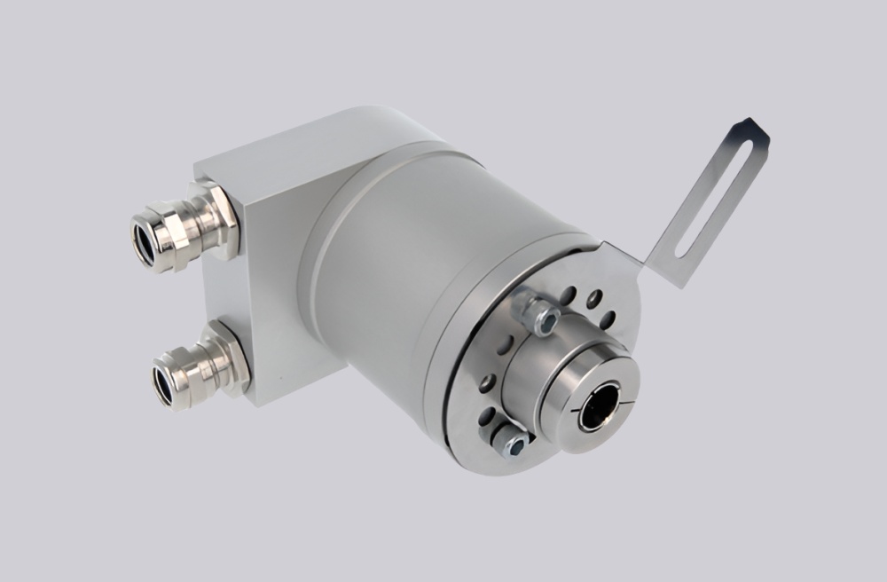
This configuration is used where an absolute encoder provides a singleturn position value through Profibus DP. The original specification combines 8192 steps per revolution, one revolution, programmable code behavior, 11–27 VDC supply, RS485 output level, IP65 protection, ZB80 flange mounting, 10FL/24 shaft style, radial 3×PG9 connection, 12 Mbaud communication, and PNO Profile Class 2 support. Replacement work should focus on Profibus address setting, GSD/profile compatibility, terminal assignment, bus A/B polarity, preset input handling, termination switch status, shield grounding, and the mechanical mounting envelope.
System Limits
The first system limit is Profibus commissioning. Node address, PNO Profile Class 2 behavior, baud-rate capability, encoder resolution, preset function, and PLC configuration must remain consistent with the installed system. If the device is accepted by the network but the profile, address, or preset behavior differs, the machine can receive a valid telegram with the wrong position meaning.
The second limit is terminal wiring and bus termination. The incoming and outgoing Profibus lines use separate screw-terminal paths, and the terminal resistance must be switched correctly when the encoder is the last station. Reversed DataA/DataB wiring, a duplicate address, missing termination, or poor shield bonding can create intermittent Profibus faults under vibration or inverter noise.
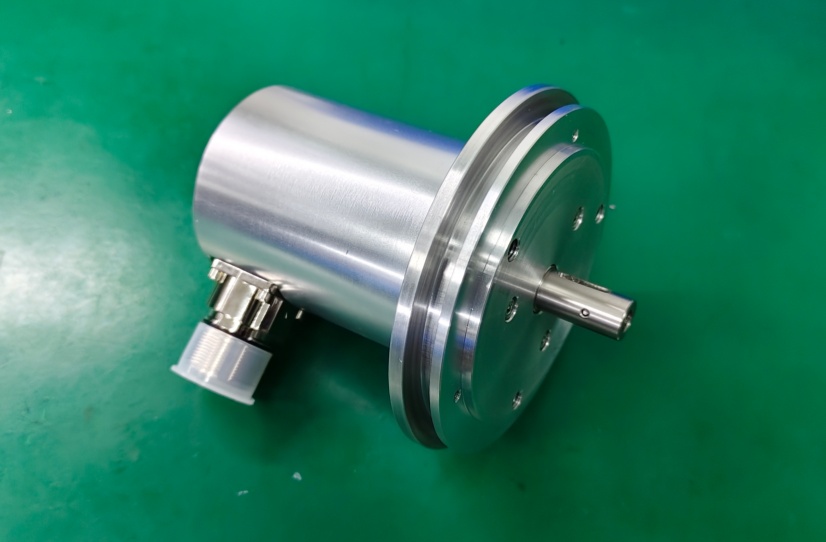
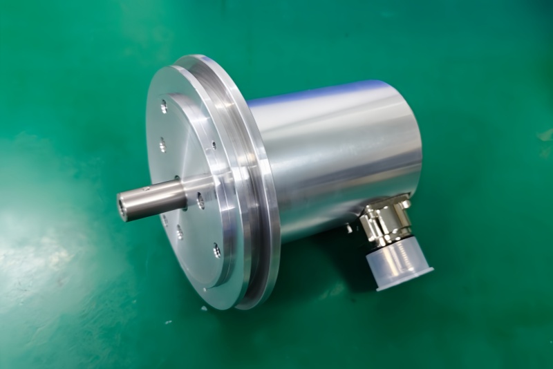
The mechanical limit is the ZB80 flange and 10FL/24 shaft interface. Shaft engagement, coupling alignment, flange centering, radial cable-gland clearance, and housing position must be checked before startup. A mechanically forced replacement can create bearing load, repeatability drift, or unstable feedback even when Profibus diagnostics appear normal.
Wiring & Installation
Before replacement, record the Profibus station address, PLC hardware configuration, GSD/profile setting, preset wiring, termination switch status, supply voltage, and terminal assignments. Confirm DataA/DataB polarity on both bus sides and verify whether the encoder is installed as the last Profibus station.
During installation, preserve the radial 3×PG9 cable entry layout and maintain shield continuity through the cable glands and cabinet grounding path. Route Profibus wiring away from motor and inverter power cables. Align the 10FL/24 shaft interface without axial force, keep the ZB80 flange square to the mounting surface, and tighten the mechanical interface without adding preload. After startup, verify online status, actual position, preset response, counting direction, address stability, bus diagnostics, and repeatability through several machine cycles.
Custom Compatible Solution
EncoderWorks can configure the replacement around the installed Profibus and mechanical system:
- Match 8192-step absolute position behavior with singleturn Profibus-DP output
- Preserve PNO Profile Class 2 compatibility, 12 Mbaud bus capability, node addressing, preset function, and diagnostic behavior
- Adapt the ZB80 flange, 10FL/24 shaft interface, IP65 housing requirement, and radial 3×PG9 wiring layout
- Review DataA/DataB polarity, terminal resistance, shield grounding, EMC routing, supply wiring, and mechanical preload
Key Data
| Item | Data |
|---|---|
| Model | CEV65S-00169 |
| Order No. | 111-00169 |
| Previous marking | CE65S 8192/1 PBS |
| Encoder type | Absolute rotary encoder |
| Interface | Profibus DP |
| Profile | PNO Profile Class 2 |
| Resolution | 8192 steps/rev |
| Revolutions | 1 |
| Code | Programmable |
| Supply voltage | 11–27 VDC |
| Output level | RS485 |
| Baud rate option | 12 Mbaud |
| Protection | IP65 |
| Operating temperature | 0–60°C |
| Flange | ZB80 |
| Shaft | 10FL/24 |
| Connection | Radial 3×PG9 |
| Pinout document | TR-ECE-TI-GB-0017 |
| Key checks | Node address, DataA/DataB, preset wiring, termination, shield grounding |