The custom compatible solution for CEV65M-11046 must protect the controller from one practical failure: the parallel position word can be present on O_D0–O_D23, but DataBus_disable_IN can force the outputs into tristate if the replacement wiring or PLC logic is not matched. A stable replacement must preserve the original bit map, latch capture, preset inputs, and bus-disable behavior before the machine can trust the absolute value. Typical production lead time: 15 working days.
Where the System Fails First
The controller reads this model as a parallel absolute position word through a 37-pin SUB-D connector. The pinout assigns O_D0 to O_D23 as the data outputs, then separates the control functions: DataBus_disable_IN, Preset1_IN, I_Latch, Direction IN, Preset2_IN, RS485 programming lines, supply voltage, and ground.
The main weak points are:
- Wrong O_D0–O_D23 mapping → corrupted absolute position
- DataBus_disable_IN active at the wrong time → outputs enter tristate
- Latch timing error → sampled transition value
- Direction input mismatch → reversed position logic
- Preset1 / Preset2 wiring error → false reference point
- SUB-D shield weakness → random bit-level noise
For CEV65M-11046, the practical replacement boundary is not only “parallel push-pull compatibility.” It is parallel word integrity plus DataBus-disable timing. If the PLC expects the outputs to remain active but the bus-disable input is driven high, the position word can disappear without any encoder core failure.
Connector and Mechanical Boundary
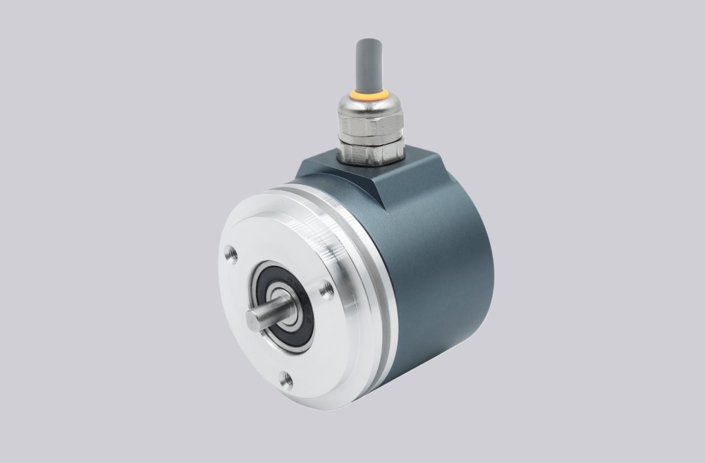
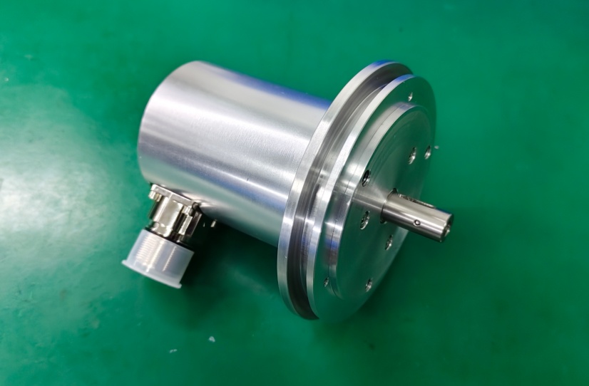
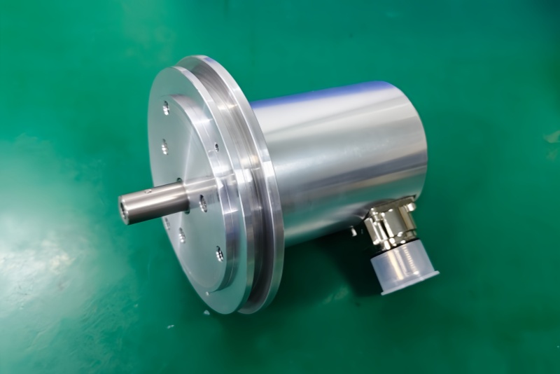
The drawing shows a ZB80 flange, 12FL / 24 shaft, 0.5 m cable, and 37-pin SUB-D connector with PG axial cable exit. This larger ZB80 mechanical format is important, but the first field failure will often appear at the connector and control-input layer, not the flange.
The short cable reduces long-distance transmission risk, but parallel outputs still depend on clean grounding, stable input reference, and proper shielding. In a cabinet with inverter noise or poor cable strain relief, one unstable data line can create a wrong position value that looks like a random encoder fault.
Installation Notes
- Keep the model format as CEV65M-11046
- Map O_D0–O_D23 by signal name before startup
- Confirm DataBus_disable_IN logic before energizing the controller
- Check I_Latch timing at the PLC input
- Verify Direction, Preset1, and Preset2 behavior
- Keep RS485 programming wires separate from parallel data outputs
- Maintain SUB-D shielding and axial cable strain relief
- De-energize the system before wiring or connector work
Key Data
- Model: CEV65M-11046
- Type: Absolute rotary encoder
- Interface: Parallel push-pull
- Code: Programmable
- Resolution: 4096 steps / revolution
- Multiturn range: 4096 revolutions
- Supply voltage: 11–27 VDC
- Output level: 11–27 VDC
- Flange: ZB80
- Shaft: 12FL / 24
- Connector: SUB-D 37-pin
- Connector position: PG axial
- Cable length: 0.5 m
- Protection: IP65
- Operating temperature: -20 °C to +70 °C
- Options: BUS, F/R, Latch, Preset 1+2, Programmable
- Pinout: ST2227A
- Parameter file: CE833-265
- Firmware: 437865