The replacement task for CEV65M-00068 is not just matching a parallel encoder; it is preserving the original binary output word, latch behavior, preset inputs, and SUB-D 37-pin wiring discipline so the controller reads the same absolute position after replacement. Typical production lead time: 15 working days.
This model uses parallel push-pull absolute feedback, not SSI, Profibus, PROFINET, CANopen, analog, or incremental output. The position is exposed as a wide binary word. If one output line is mapped incorrectly, the controller may still see active signals, but the position value will be wrong.

Where the System Fails First
The pinout defines O_D0 to O_D23 as data outputs, with Preset1_IN, Preset2_IN, I_Latch, Direction IN, RS485 programming lines, supply voltage, and ground. The main integration risk is therefore not resolution; it is whether the PLC input side captures all 24 data lines at the correct moment.
The weak points are direct:
- Wrong O_D0–O_D23 mapping → corrupted binary position
- Latch timing error → unstable sampled value
- Wrong Direction input → reversed position logic
- Preset1 / Preset2 wiring error → false reference point
- RS485 programming pair mixed with output wiring → commissioning fault
- SUB-D shield weakness → random bit-level noise
Unlike versions with DataBus control, this pinout does not show a DataBus input. That means the replacement focus should stay on bit mapping, latch timing, preset logic, and connector stability, not tristate bus control.
Connector and Wiring Boundary
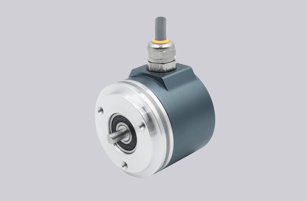
The drawing shows a ZB36 flange, 10FL / 19.5 shaft, 0.5 m cable, and 37-pin SUB-D connector with PG axial cable exit. The short cable reduces long-distance loss, but the connector remains the practical failure boundary. A loose SUB-D shell, poor shield path, or strained axial cable can create bit errors before the encoder body itself fails.
The protection level is IP54, so the connector and cable side should be protected from dust-heavy, wet, oily, or washdown environments. In cabinet installations with inverter noise, parallel push-pull lines must be routed away from motor power wiring and relay switching circuits.
Installation Notes
- Keep the model format as CEV65M-00068
- Map O_D0–O_D23 exactly at the controller input
- Confirm binary decoding before startup
- Check I_Latch timing before replacing the encoder
- Verify Direction, Preset1, and Preset2 logic
- Keep RS485 programming wires separate from parallel data lines
- Maintain SUB-D shielding and axial cable strain relief
- De-energize the system before wiring or connector work
Key Data
- Model: CEV65M-00068
- Type: Absolute rotary encoder
- Interface: Parallel push-pull
- Code: Binary
- Resolution: 4096 steps / revolution
- Multiturn range: 4096 revolutions
- Supply voltage: 11–27 VDC
- Output level: 11–27 VDC
- Flange: ZB36
- Shaft: 10FL / 19.5
- Connector: SUB-D 37-pin
- Connector position: PG axial
- Cable length: 0.5 m
- Protection: IP54
- Temperature range: -20 °C to +70 °C
- Options: F/R, Latch, Preset 1+2, Programmable
- Pinout: ST270B
- Parameter file: CE833-265
- Firmware: 43770D