

For 8.H120.356A.1024.0020, EncoderWorks can provide a custom compatible replacement focused on 10–30 V push-pull receiver matching, 1024 PPR scaling, Ø25 mm through-hollow-shaft fit, and 100 mm torque-arm installation. This model should not be treated as a light-duty incremental encoder. The main replacement risk is whether A/B/0 and inverted channels remain correct under long-cable, high-load, heavy-motor conditions.
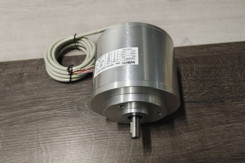
The 8.H120.356A.1024.0020 is a heavy-duty optical incremental hollow-shaft encoder configuration with 1024 PPR, push-pull output with inverted signals, 10–30 VDC supply, power-type cable capability, Ø25 mm through hollow shaft, 100 mm torque arm, radial PVC cable connection, and special 2 m cable length. The controller must keep the same 1024 PPR scaling and quadrature interpretation.
The first failure boundary is signal-chain matching. A, B, 0 and inverted A/B/0 must be wired by function, not only by connector position or cable color. If receiver threshold, reference-pulse logic, inverted channels, or pulse scaling is wrong, the machine can count in the wrong direction or lose position at speed.
This replacement fails when A/B/0 signals are present, but the controller loses counts or reads the wrong motion value because push-pull output behavior, 1024 PPR scaling, cable shielding, inverted-channel mapping, or reference-pulse handling does not match the original encoder.
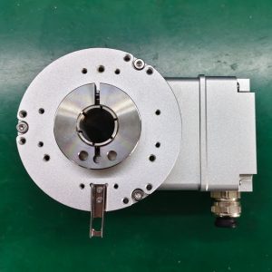
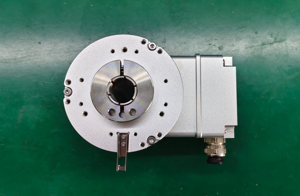
The second boundary is heavy-duty hollow-shaft mechanics. The Ø25 mm through shaft, torque arm length, clamp-ring torque, shaft fit, radial load, axial load, and cable strain must be checked together. High shaft-load capacity does not allow forced misalignment or preload through the torque arm.
The replacement decision should first confirm 1024 PPR scaling, 10–30 V push-pull receiver compatibility, A/B/0 plus inverted channel mapping, 300 kHz frequency margin, radial 2 m cable assignment, Ø25 mm through-hollow-shaft fit, 100 mm torque-arm geometry, clamp-ring tightening, IP67 sealing, shield grounding, cable routing, and shaft-load limits. EncoderWorks treats 8.H120.356A.1024.0020 as an industrial encoder custom compatible solution where push-pull signal integrity and heavy-duty hollow-shaft installation decide field reliability.
Typical production lead time: 15 working days.
Key Data
| Item | Data |
|---|---|
| Model | 8.H120.356A.1024.0020 |
| Encoder type | Heavy-duty incremental hollow-shaft encoder |
| Detection type | Optical |
| Pulse count | 1024 PPR |
| Output circuit | Push-pull with inverted signals |
| Signal output | A, B, 0 and inverted A, B, 0 |
| Supply voltage | 10–30 VDC |
| Max pulse frequency | 300 kHz |
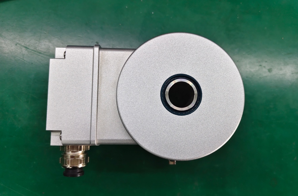
| Shaft type | Through hollow shaft |
| Shaft size | Ø25 mm |
| Mounting | 100 mm torque arm |
| Connection | Radial PVC cable, special length |
| Cable length | 2 m |
| Protection class | IP67 |
| Main engineering anchor | Push-pull output and Ø25 hollow shaft |
| Main failure boundary | Wrong channel mapping, receiver mismatch, scaling error, torque-arm preload |