


A tailored compatible encoder solution can be developed for AVM14N-05MK2A0BN-1212 in maintenance, retrofit, replacement, and upgrade applications. This model is a multiturn absolute encoder with SSI output, a Ø12 mm solid shaft, axial 2 m cable, and binary code format. Typical production lead time: 15 working days. The engineering focus is to preserve binary-code handling, SSI clock/data matching, and pulley-side shaft installation continuity during replacement.
Technical Overview of the AVM14N-05MK2A0BN-1212 Encoder
The AVM14N-05MK2A0BN-1212 belongs to the same multiturn SSI platform but uses binary code output instead of Gray code. This coded version uses a Ø12 mm x 25 mm solid shaft with 40 mm fit, clamping flange, axial cable exit, 2 m cable, and a 12 bit singleturn plus 12 bit multiturn structure with 24 bit overall resolution.
The encoder transfers position data synchronously to the control module clock and uses a galvanically isolated RS 422 interface. The platform also supports function inputs for counting direction and zero setting, which makes it suitable for systems where position logic and commissioning behavior must remain aligned with the original installation.
Industrial Integration Considerations
For this binary-output version, controller-side data interpretation is the main compatibility factor. In many installed systems, SSI processing, scaling, and software-side position handling are already configured around binary code rather than Gray code. That means replacement planning should preserve not only the mechanical platform, but also the expected output-code logic already used by the control system.
The mechanical structure remains important as well. The shaft includes a feather key groove and is suitable for receiving a belt pulley or similar device. Together with the clamping flange, Ø40 mm / Ø80 mm centering shoulders, and 3 x M6 mounting holes, this makes flange-side positioning and pulley-mounting continuity a meaningful part of engineering matching.
Field Installation and Wiring Notes
SSI wiring should be checked against the original controller timing and cable length. The datasheet specifies four signal lines for clock and data, plus dedicated lines for preset and counting direction. If the original installation already uses fixed input polarity for preset and cw/ccw selection, those logic conditions should be preserved during replacement. The counting-direction input is activated with 0-level, and the preset input is activated with 1-level.
Because this is an axial cable version, rear cable routing should remain aligned with the original machine layout. Cable bending, compression, and tensile load should be avoided during installation so that SSI signal quality and cable life remain stable.
Custom Compatible Encoder Solution
A custom compatible encoder solution for AVM14N-05MK2A0BN-1212 should preserve five engineering points: Ø12 mm shaft geometry with 40 mm fit, clamping flange mounting, 2 m axial cable route, binary SSI output, and the 12 bit singleturn plus 12 bit multiturn structure. This supports both controller-side data continuity and stable mechanical replacement in the field.
Where the installed application uses preset logic, counting-direction switching, pulley mounting, or fixed SSI timing conditions, those elements should be confirmed during engineering review before final production is released.
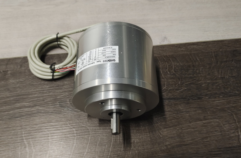
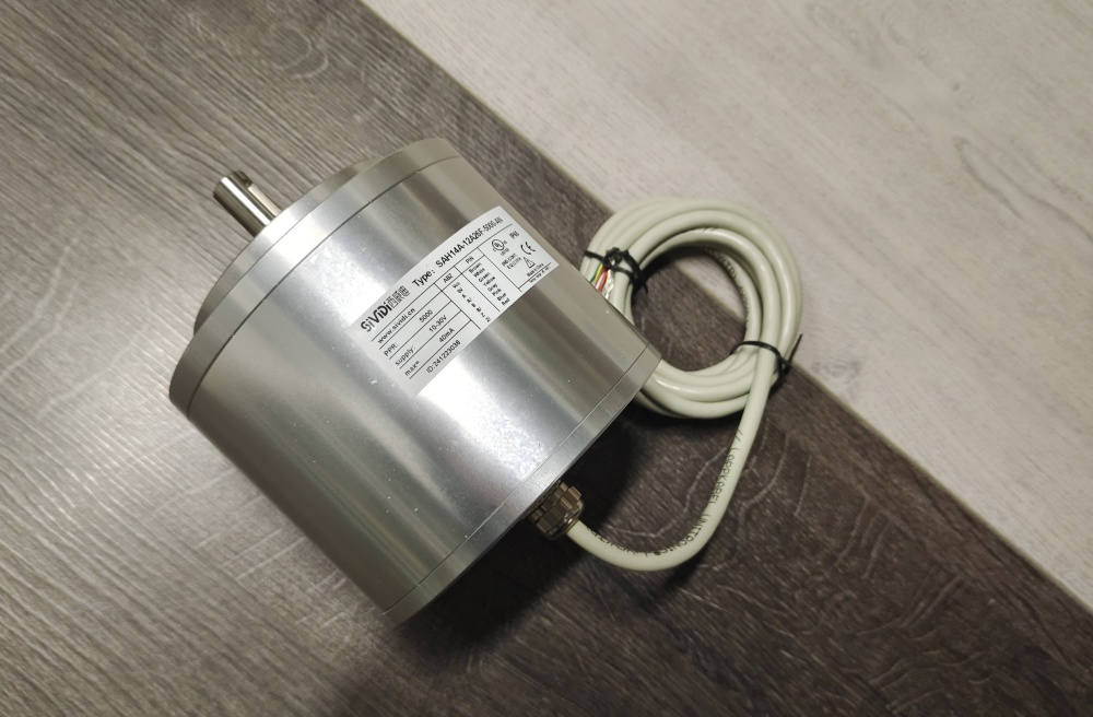
Custom Solution Photos
Lead Time and Custom Development
Typical production lead time: 15 working days.
Key checkpoints should include shaft diameter, feather key groove compatibility, flange reference, axial cable clearance, SSI line length versus baud rate, binary-code requirement, and original input logic for preset and counting direction.
Typical Technical Parameters
| Parameter | Specification |
|---|---|
| Encoder Type | Multiturn absolute encoder |
| Model | AVM14N-05MK2A0BN-1212 |
| Interface | SSI |
| Standard Conformity | RS 422, galvanically isolated |
| Singleturn Resolution | 12 bit |
| Multiturn Resolution | 12 bit |
| Overall Resolution | 24 bit |
| Output Code | Binary |
| Transfer Rate | 0.05 ... 1.5 MBit/s |
| Monoflop Time | 20 ± 10 µs |
| Clock Pause | > 25 µs |
| Input 1 | Counting direction (cw/ccw) |
| Input 1 Logic | Activated with 0-level |
| Input 2 | Zero-set (PRESET 1) |
| Input 2 Logic | Activated with 1-level |
| Supply Voltage | 10 ... 30 V DC |
| Shaft Type | Solid shaft |
| Shaft Dimension | Ø12 mm x 25 mm |
| Fit Reference | 40 mm fit |
| Flange Version | Clamping flange |
| Connection Type | Cable Ø11.2 mm, 9-core, 2 m |
| Exit Position | Axial |
| Housing Material | Aluminum, powder coated |
| Protection Rating | IP66 |
| Operating Temperature | Gas Ex-area -40 ... +55 °C / Dust Ex-area -30 ... +55 °C |
| Storage Temperature | Gas Ex-area -40 ... +70 °C / Dust Ex-area -30 ... +70 °C |
| Max. Speed | 6000 min⁻¹ |
| Shaft Load | 60 N axial / 80 N radial |


