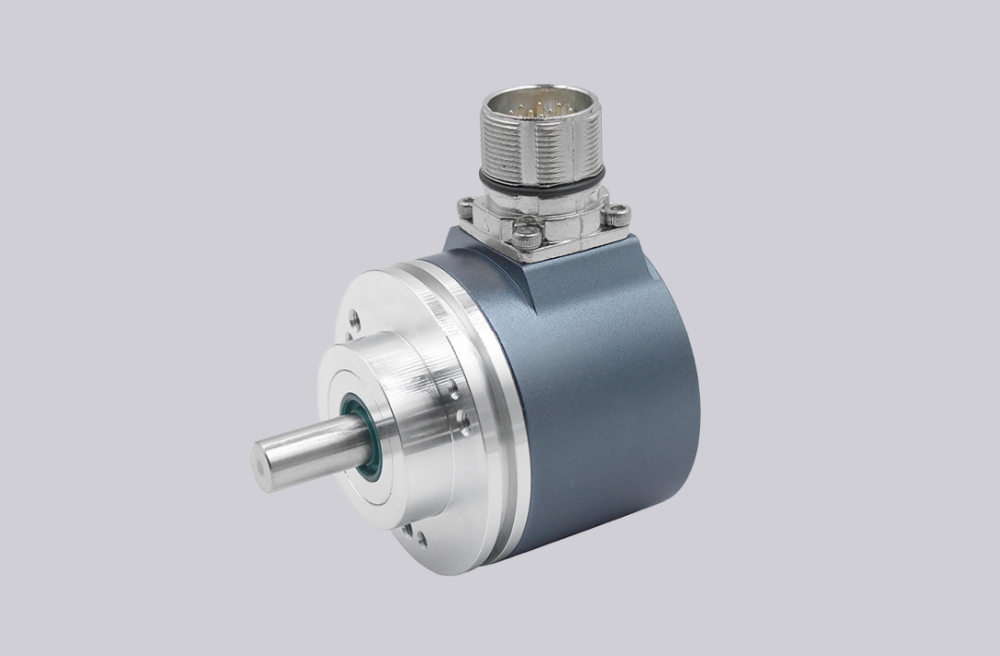
For GXM7W.1102101, EncoderWorks can provide a custom compatible replacement focused on RS485 radial cable routing, address-coded bus communication, and Ø6 mm synchro-flange alignment. This model should not be treated as an SSI encoder or a simple absolute encoder exchange. The replacement risk is that the encoder may power up and respond on the bus, while the master still receives the wrong position or no valid reply because IN/OUT wiring, address coding, zero setting, or shaft coupling has changed.
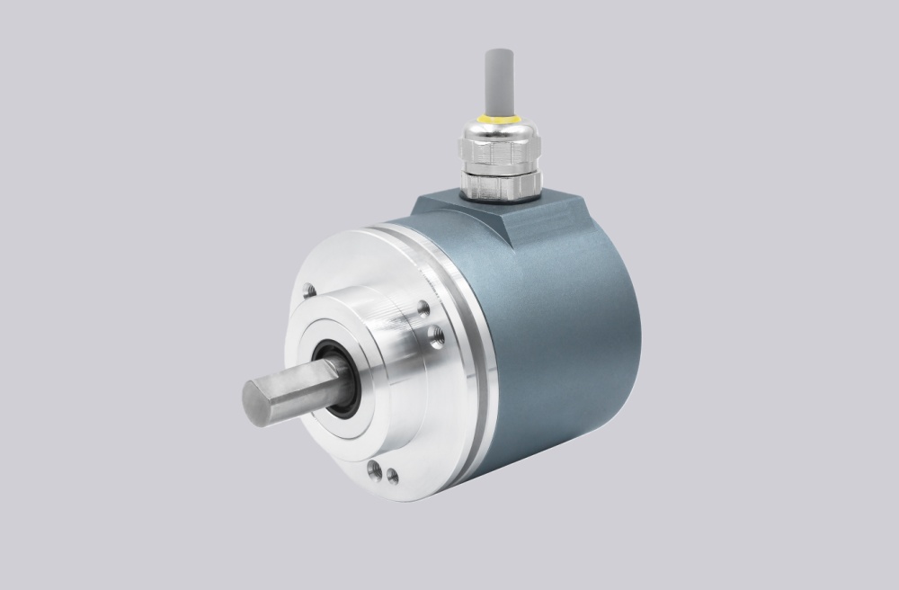
The GXM7W.1102101 is an RS485 multiturn absolute encoder configuration with optical sensing, 13-bit singleturn resolution, 12-bit multiturn range, binary code, 10–30 VDC supply, Ø58 mm housing, Ø6 mm synchro flange, IP54 mechanical execution, and radial 1 m cable connection. Its position data should be handled as 8192 steps per turn and 4096 turns, not as a generic serial encoder word.
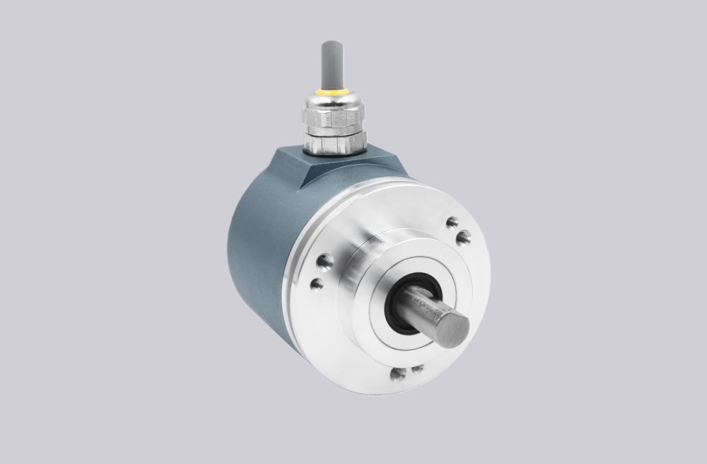
The first failure boundary is RS485 bus wiring. The interface uses separate T/R IN and T/R OUT signal paths to avoid stub lines. If the arriving and departing bus pairs are crossed, or if the encoder is the final bus user but termination is not handled correctly, the master/slave exchange can become unstable even when the encoder electronics are healthy.
This replacement fails when the encoder is powered, but the controller receives no valid position because T/R+ IN, T/R- IN, T/R+ OUT, T/R- OUT, address coding, or bus termination does not match the original installation. That is a bus-chain failure, not an optical sensing failure.
The second boundary is address coding. The RS485 address is coded by connection through Ident 1 and Ident 2, with address values in the small bus range. If the Ident lines are copied incorrectly, the encoder may answer as another node or fail to answer the expected master request. The master command and encoder reply must remain compatible with the original polling format, checksum logic, and 38.4 kBaud serial setting.
Zero setting and UP/DOWN direction also need control. A zero-setting high pulse can change the electrical reference, while UP/DOWN changes the counting direction. If either line is left in a different state, the bus reply may be valid while the machine position is wrong.
Mechanically, the Ø6 mm synchro flange requires accurate coupling alignment. The shaft should not be used to correct eccentricity or angular error. Radial cable exit also needs enough bend clearance so cable strain does not disturb the small synchro-shaft installation.
The replacement decision should first confirm Ø6 mm synchro-flange geometry, IP54 requirement, radial cable assignment, RS485 38.4 kBaud setting, T/R IN and OUT wiring, final-node termination, Ident 1/2 address coding, 13-bit singleturn and 12-bit multiturn mapping, zero-setting input, UP/DOWN direction, supply voltage, shielding, and coupling load. EncoderWorks treats GXM7W.1102101 as an industrial encoder custom compatible solution where RS485 bus identity and synchro-flange mechanics decide field reliability.
Typical production lead time: 15 working days.
Key Data
| Item | Data |
|---|---|
| Model | GXM7W.1102101 |
| Encoder type | Multiturn absolute encoder |
| Interface | RS485 bus interface |
| Transmission rate | 38.4 kBaud |
| Sensor technology | Optical |
| Resolution | 13-bit singleturn + 12-bit multiturn |
| Steps / turns | 8192 steps per turn / 4096 turns |
| Code | Binary |
| Supply voltage | 10–30 VDC |
| Housing | Ø58 mm steel housing |
| Shaft / flange | Ø6 mm synchro flange |
| Protection class | IP54 |
| Connection | 1 m radial cable |
| Control inputs | Zero setting, UP/DOWN direction, Ident 1/2 address coding |
| Main engineering anchor | RS485 radial cable and synchro flange |
| Main failure boundary | Wrong IN/OUT wiring, address mismatch, zero-set error, coupling preload |
Related Models
GXM7W.1101101 RS485 Multiturn Absolute Encoder
GXM7W.110A001 RS485 Absolute Encoder Solution
GXM7W.110A101 Multiturn Absolute Encoder