EncoderWorks develops a concise custom compatible solution for PAM90P1C-BF6XXR-4096/8192, focused on preserving Profibus-DP Class 2 feedback while matching the P1C flange-style mechanical interface. The replacement fails when the PLC address, baud communication, and resolution scaling are restored, but the flange centering, mounting hole pattern, shaft alignment, or shield grounding is treated like a standard hollow-shaft support version. Typical production lead time: 15 working days.
Where the System Fails First
The controller reads PAM90P1C-BF6XXR-4096/8192 as a Profibus-DP absolute multiturn encoder. The model code indicates the PAM90 large-frame platform, binary code, F6 Profibus Class 2 interface, radial outlet direction, and 4096 / 8192 resolution configuration. The reference document identifies key Profibus commissioning points such as DIP-switch address setting, terminal resistance, RS485 bus wiring, preset, rotation direction, scaling factor, singleturn resolution, total resolution, and diagnostic mode.
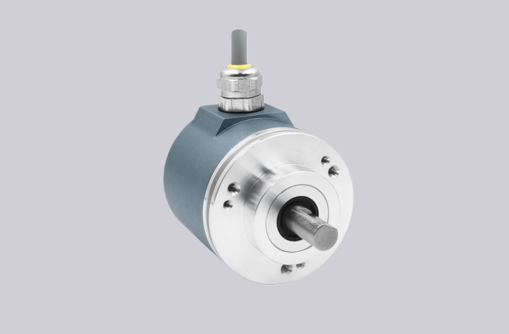
This replacement fails when the encoder is selected only by Profibus protocol and resolution. The P1C mechanical layout is different from torque-arm or bracket-supported versions. The mounting face must locate the encoder correctly; if the flange is used to force alignment, shaft stress or bearing load can appear before any electrical fault is visible.
The first checks should remain practical: restore the Profibus address, confirm A/B line polarity, use terminal resistance only at the end of the bus, and maintain shield continuity. Then verify the flange centering, mounting screws, shaft fit, and radial cable clearance. A stable bus does not prove that the mechanical replacement is safe.
A stable replacement must first reproduce the original Profibus identity, flange mounting geometry, and shaft alignment before the position value can be trusted.
P1C Mechanical and Bus Boundary
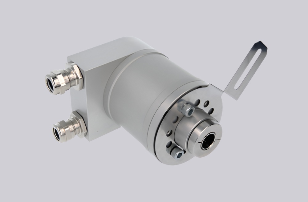
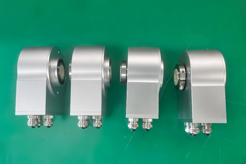
The PAM90P reference shows multiple mechanical styles, including PAM90P1C, with a compact flange-style drawing and defined mounting geometry. The same document lists 10–30 VDC supply, IP65 protection, 12 Mbit/s maximum Profibus transmission rate, Profibus encoder profile Class 2 behavior, and configurable resolution functions through the controller side.
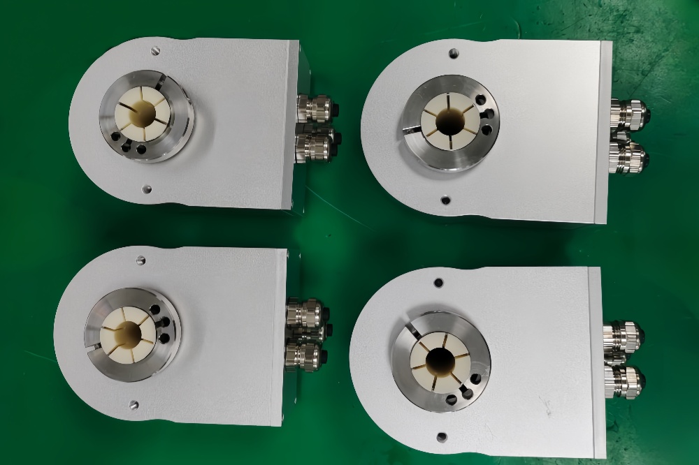
For PAM90P1C-BF6XXR-4096/8192, the unique checkpoint is not bore size alone. It is the flange-mounted mechanical boundary. If the encoder is installed with uneven screw load, poor centering, or cable tension at the radial outlet, the system may show unstable feedback even though the Profibus telegrams remain valid.
Installation Notes
- Keep the model format as PAM90P1C-BF6XXR-4096/8192
- Confirm the P1C flange mounting geometry before startup
- Restore the original Profibus station address by DIP switch
- Enable terminal resistance only at the last bus station
- Keep Profibus A/B wiring polarity unchanged
- Maintain shield continuity through the connection area
- Check shaft alignment and mounting screw load
- Confirm PLC scaling for 4096 / 8192 resolution configuration
Key Data
- Model: PAM90P1C-BF6XXR-4096/8192
- Type: Absolute multiturn encoder
- Interface: Profibus-DP
- Profile: Encoder Profile Class 2
- Code: Binary
- Resolution configuration: 4096 / 8192
- Supply voltage: 10–30 VDC
- Communication: RS485
- Max transmission rate: 12 Mbit/s
- Mechanical style: P1C flange-mounted configuration
- Connector direction: R = radial outlet
- Protection: IP65
- Main replacement focus: flange centering, shaft alignment, Profibus address, termination, shielding
- Adjustable functions: rotation direction, scaling factor, singleturn resolution, total resolution, preset, diagnostic mode