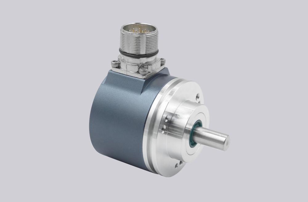
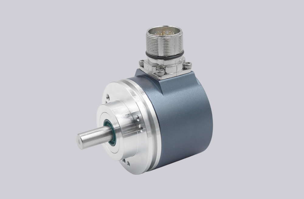
FG4S-1024G-90G-NG should be specified as a preferred nickel-disk FG 4 encoder with a single 15-pole industrial plug, where EncoderWorks can configure a custom compatible replacement solution around the 1024 PPR scaling, S plug pinout, A/B 90° phase relationship, inverted signal pairs, N marker repeatability, shielded plug wiring, and coupling preload. The main failure boundary is a feedback system that counts pulses normally but loses speed accuracy, direction logic, or zero recovery because the 1024 PPR reference, marker channel, or plug pin assignment is not preserved. Typical production lead time: 15 working days.
This configuration belongs to the FG 4 optical incremental encoder platform for heavy-duty industrial environments. It uses 1024 pulses per revolution, square-wave output, a 0° basic channel, a second channel electrically shifted by 90°, inverted outputs for industrial signal transmission, and an N marker pulse with inverted marker signal. The S version should be handled as a single 15-pole industrial plug encoder, not as an SS redundant dual-plug unit or a K terminal-box version. Replacement work should focus on plug pin assignment, shield continuity, supply integrity, counter input compatibility, A/B phase sequence, marker interpretation, and mechanical alignment.
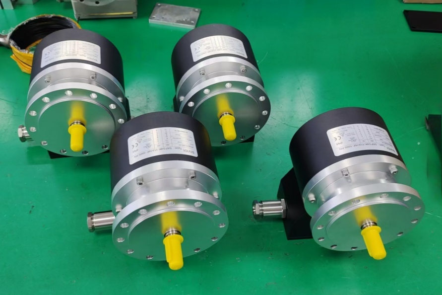
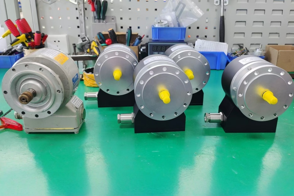
System Limits
The first system limit is 1024 PPR reference scaling. A controller configured for 800, 1000, 1200, 2000, or another pulse count may still receive stable A/B signals, but speed, travel, and synchronization values will be wrong. Edge-counting mode, speed conversion, and direction logic should be confirmed before startup.
The second limit is N marker repeatability through the single plug. The 15-pole plug must preserve A, /A, B, /B, N, and /N exactly as expected by the controller. If one phase pair is swapped, one inverted signal is missing, or the marker input is assigned to a different pin, the machine may run but fail during homing, zero return, or synchronized positioning.
The third limit is plug shielding and mechanical preload. The S plug format has a different installation boundary from a terminal box. Plug seating, cable strain, shield bonding, moisture protection, and pin contact condition must be checked. Coupling misalignment, axial preload, radial load, or shaft shock can shorten bearing life and create pulse jitter even when the counter frequency margin is wide.
Wiring & Installation
Before replacement, record the 15-pole plug pinout for the basic channel, 90° channel, marker pulse, inverted signals, supply voltage, GND, shield connection, LED-check or diagnostic output if used. Confirm that the receiving counter is scaled for 1024 PPR and that the machine logic does not rely on another reference resolution.
During installation, fit the coupling smoothly and do not strike the shaft or housing. Keep the encoder centered, control angular and parallel offset, and avoid axial preload. Route A-/A, B-/B, and N-/N through paired shielded conductors, keep the cable away from inverter output, motor, brake, and contactor wiring, and avoid lateral cable stress at the plug. After commissioning, verify pulse count, speed scaling, direction, N marker repeatability, plug seating, shield continuity, and signal stability through the operating speed range.
Custom Compatible Solution
EncoderWorks can configure the replacement around the installed counter and plug interface:
- Match 1024 PPR square-wave incremental output with 0°/90° channel behavior and inverted signal pairs
- Preserve S single 15-pole industrial plug structure, N marker behavior, supply range, output level, and controller input compatibility
- Adapt the FG 4 mechanical envelope, shaft interface, flange or foot mounting requirement, coupling alignment, and plug cable layout
- Review 100 kHz / 150 kHz frequency margin, shielded twisted-pair routing, plug pin mapping, bearing load, and marker repeatability
Key Data
| Item | Data |
|---|---|
| Model | FG4S-1024G-90G-NG |
| Encoder type | Heavy-duty optical incremental encoder |
| Series | FG 4 |
| Connection structure | S single 15-pole industrial plug |
| Pulses per revolution | 1024 PPR |
| Pulse disk class | Preferred nickel-disk pulse rate |
| Signal output | Square wave, 0° and 90° channels |
| Inverted signals | Yes, Option G |
| Marker pulse | Option N with inverted marker signal |
| Plug capacity | Up to 13 outputs |
| Plug protection boundary | IP55 |
| Supply voltage | 12–30 VDC |
| Output type | Differential line driver / push-pull style output |
| Frequency range | 0–100 kHz standard, up to 150 kHz if specified |
| Standard shaft | Ø11j6 × 30 mm |
| Optional shaft | Ø14j6 × 30 mm |
| Key checks | 1024 PPR scaling, N marker repeatability, single 15-pole plug pinout, A/B phase, plug shielding |