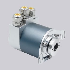
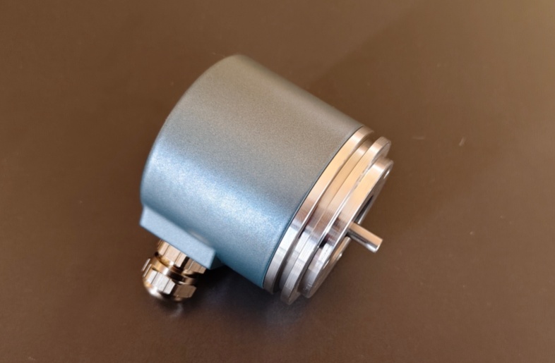
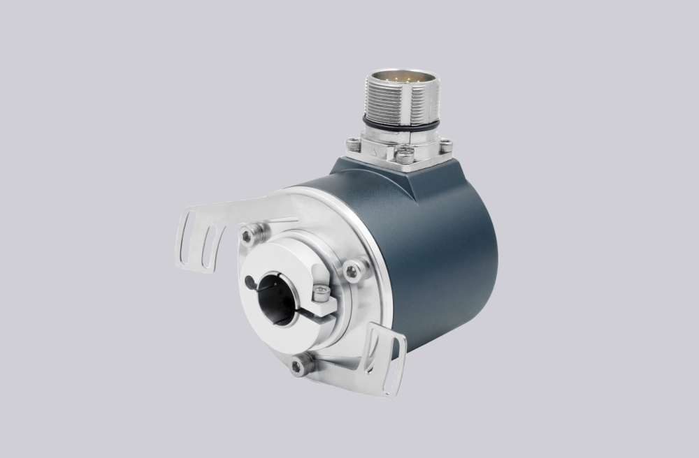
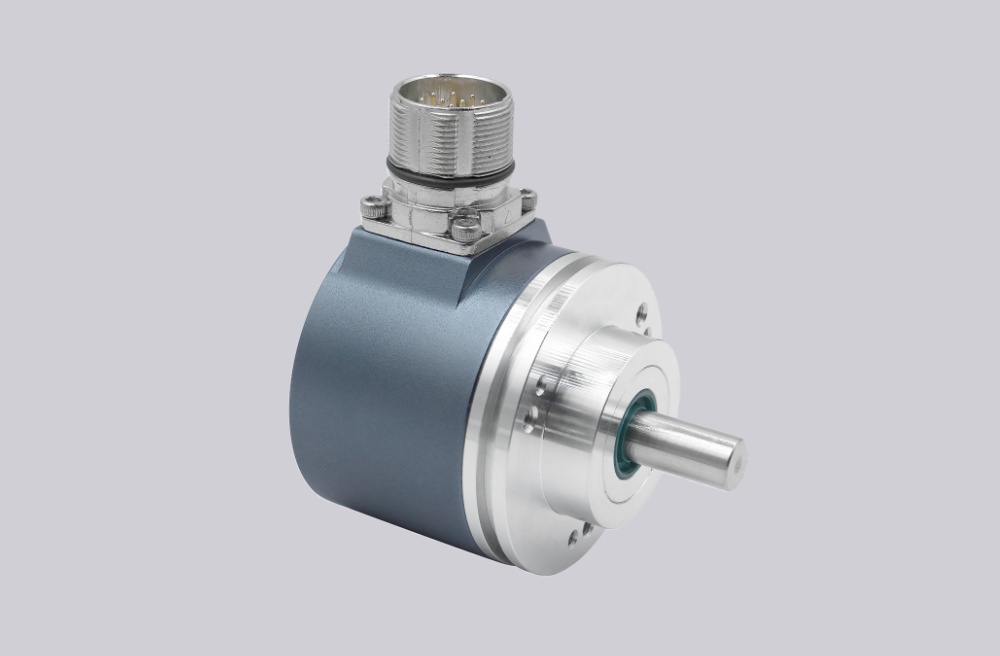
EncoderWorks develops a custom compatible replacement solution for RVI58N-011K1R61N-5000 focused on maintaining 5000 PPR incremental feedback, K1 mounting configuration, R61 signal assignment, phase-consistent A/B evaluation, reference pulse handling, and stable industrial installation. The replacement boundary is not only resolution matching, but also controller counter capability, output signal compatibility, cable integrity, shield grounding, shaft coupling accuracy, and EMC stability. Typical production lead time: 15 working days.
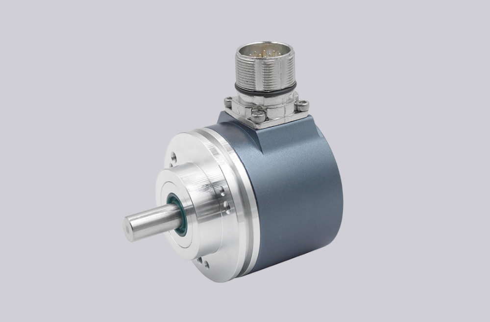
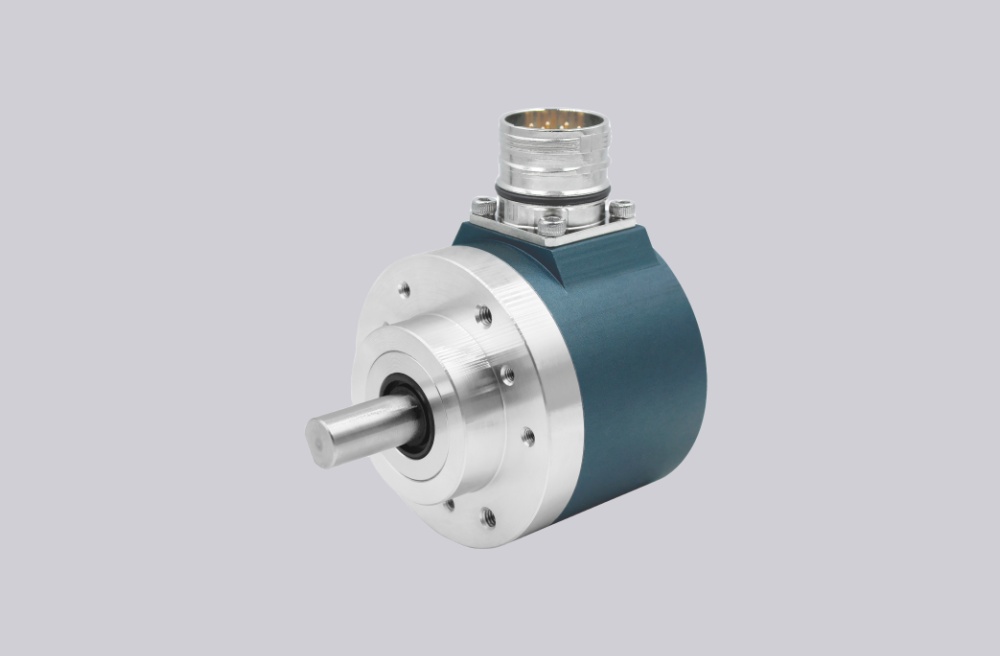
RVI58N-011K1R61N-5000 is designed for industrial motion feedback systems where high-resolution incremental signals are used for speed, position, and direction monitoring. A compatible replacement must preserve the 5000 pulses per revolution, quadrature signal relationship, output circuit compatibility, connector or cable assignment, Ø10 mm shaft interface, K1 flange mounting condition, and machine-side grounding concept.
System Limits
The first system boundary is the high-frequency incremental feedback path. At 5000 PPR, the controller must have sufficient counter frequency margin, correct A/B phase interpretation, and stable edge detection capability. A replacement may appear electrically connected while still failing when the drive receives incorrect pulse scaling, unstable direction recognition, excessive signal distortion, or insufficient noise margin at operating speed.
The second boundary is the R61 signal configuration, cable routing, shielding, and mechanical installation. The output channels, supply reference, signal ground, and shield continuity must remain consistent with the original machine wiring. Poor grounding, long cable runs near inverter equipment, or incorrect cable termination can create intermittent counting errors even when the encoder output frequency remains within the expected range.
The mechanical boundary is also critical for this compact encoder structure. The Ø10 mm shaft, flange mounting, coupling alignment, and axial/radial load condition must remain controlled. Incorrect shaft alignment or coupling preload can introduce vibration, bearing stress, and unstable feedback signals during machine operation.
Wiring & Installation
Before replacement, confirm the complete installed configuration, including 5000 PPR requirement, output level, A/B channel direction, reference signal requirement, supply voltage, cable assignment, shield termination method, shaft diameter, flange mounting condition, coupling type, and available installation space.
During installation, verify the A/B phase direction before commissioning and confirm the controller receives the correct counting direction. Keep encoder wiring separated from motor, brake, inverter, and high-current cables. The shield should maintain a short and low-resistance grounding path to reduce EMC interference.
The Ø10 mm shaft must be installed with correct coupling alignment. The mounting flange should only provide rotational restraint and should not introduce mechanical correction force. Installation errors may appear as unstable speed feedback, phase variation, or intermittent counter loss.
Custom Compatible Solution
- Match 5000 PPR incremental feedback, quadrature signal logic, and controller counter requirements
- Preserve R61 signal assignment, output compatibility, cable integrity, shield continuity, and grounding path
- Adapt Ø10 mm shaft interface, K1 flange mounting, coupling alignment, and mechanical installation conditions
- Validate frequency margin, phase accuracy, EMC exposure, wiring assignment, and commissioning parameters before shipment
Key Data
| Item | Data |
|---|---|
| Model | RVI58N-011K1R61N-5000 |
| Encoder type | Incremental solid-shaft encoder |
| Resolution | 5000 PPR |
| Signal format | Quadrature A/B incremental feedback |
| Output signals | R61 configuration, signal assignment requires matching |
| Mounting | K1 flange configuration |
| Shaft interface | Ø10 mm solid shaft |
| Main signal boundary | Counter frequency margin and phase stability |
| Mechanical focus | Shaft coupling alignment and flange mounting |
| EMC focus | Shield continuity and grounding path |
| Application check | Controller input type, output level, wiring assignment |
| Replacement focus | Pulse scaling, signal timing, cable mapping, mechanical fit |