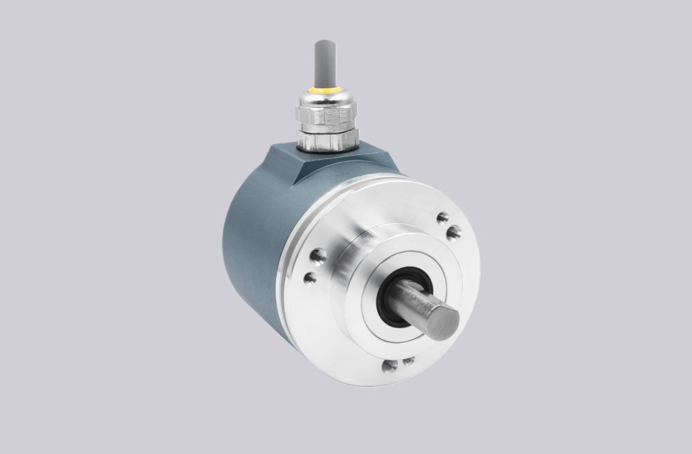
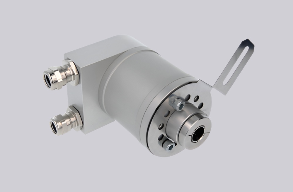
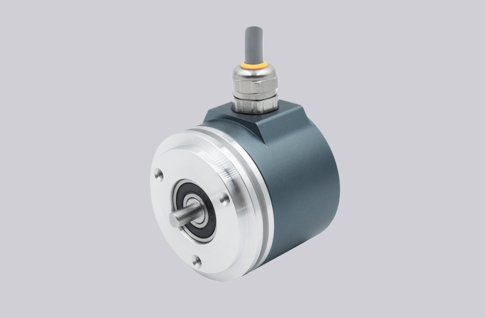
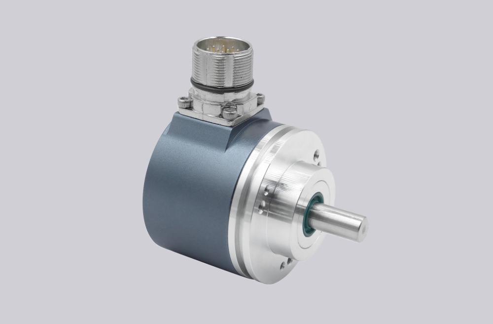
For CBE66-4096GKA06, EncoderWorks can provide a custom compatible replacement solution for 12-bit parallel absolute feedback systems where the key checks are Gray-code bit mapping, latch behavior, enable input logic, and code-sense direction control. The replacement must be verified at the controller input, because one swapped bit, wrong enable state, or reversed code-sense line can create valid-looking but incorrect position data. Typical production lead time: 15 working days.
This encoder is used where a PLC, counter module, or legacy control board reads one-turn absolute position through individual parallel conductors instead of SSI, Profibus, CANopen, or Profinet. Replacement work should treat the encoder as a complete wiring and logic interface. The 12-bit output order, Gray-code reading, latch input, enable input, code-sense state, common reference, D-Sub pin assignment, shielding, and controller input threshold must all be checked before the machine returns to service.
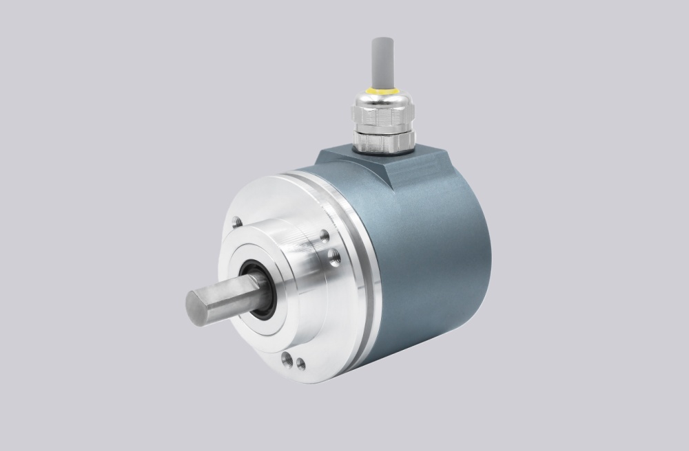
System Limits
The main system limit is 12-bit parallel bit integrity. Bit 1 through Bit 12 must be connected to the correct controller inputs, with Bit 1 as LSB and Bit 12 as MSB. A high-order bit error can create a large angular jump, while a low-order bit fault may appear as repeated indexing drift or small position error.
The second limit is latch and enable logic. The latch input stores the position value when active, while the enable input can deactivate the encoder output. If either input is wired with the wrong logic state, the controller may read frozen data, high-impedance output, or unstable position values.
The third limit is code-sense and noise control. The controller must read Gray code with the expected CW or CCW direction. The D-Sub common, supply, 0V, and shield path should be checked carefully, because parallel lines are sensitive to inverter, motor, brake, or contactor noise.
Wiring & Installation
Before removing the existing encoder, record the D-Sub 25-pin assignment, Bit 1–Bit 12 order, latch state, enable state, code-sense connection, common reference, supply voltage, shield connection, and mechanical zero position. The replacement should be wired by pin function rather than by assumed cable order.
After installation, rotate the shaft slowly through one full revolution and confirm that the controller value changes smoothly from the correct zero point. Then test latch, enable, and code-sense behavior under the real machine operating condition.
Custom Compatible Solution
EncoderWorks can configure the replacement around the installed parallel feedback system:
- Match 12-bit parallel output, Gray-code reading, D-Sub pinout, and controller input mapping
- Verify latch behavior, enable logic, code-sense direction, and controller-side value trend
- Adapt housing, shaft coupling, connector arrangement, and machine-side wiring requirement
- Review common reference, shield grounding, cable routing, and input threshold for stable operation
Key Data
| Item | Data |
|---|---|
| Model | CBE66-4096GKA06 |
| Encoder type | Absolute singleturn encoder |
| Interface | Parallel |
| Resolution | 4096 positions per 360° |
| Measurement range | 1 turn |
| Output code | Gray |
| Output bits | 12 bit, Bit 1 LSB to Bit 12 MSB |
| Supply voltage | 11–30 VDC |
| Connection | D-Sub, 25-pin socket |
| Logic functions | Latch, Enable, Code sense |
| Operating temperature | -20°C to +60°C |