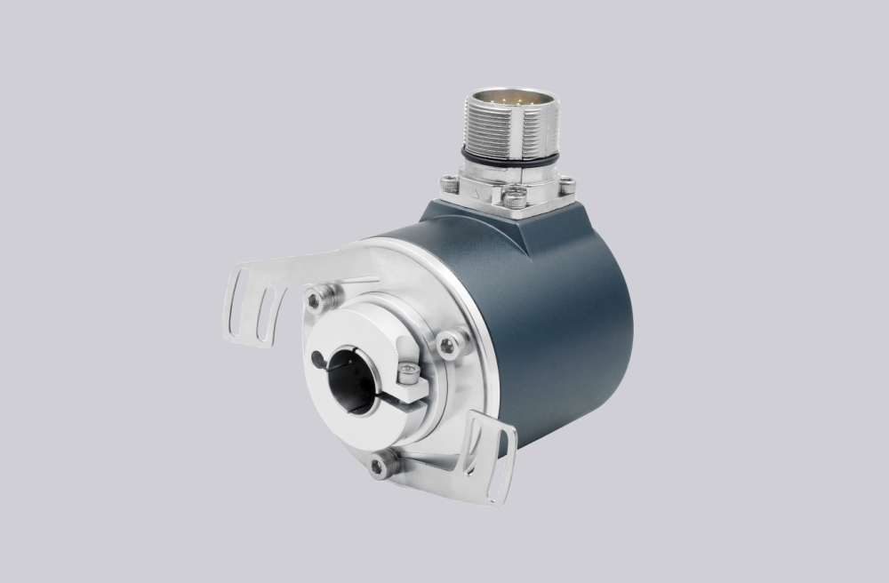
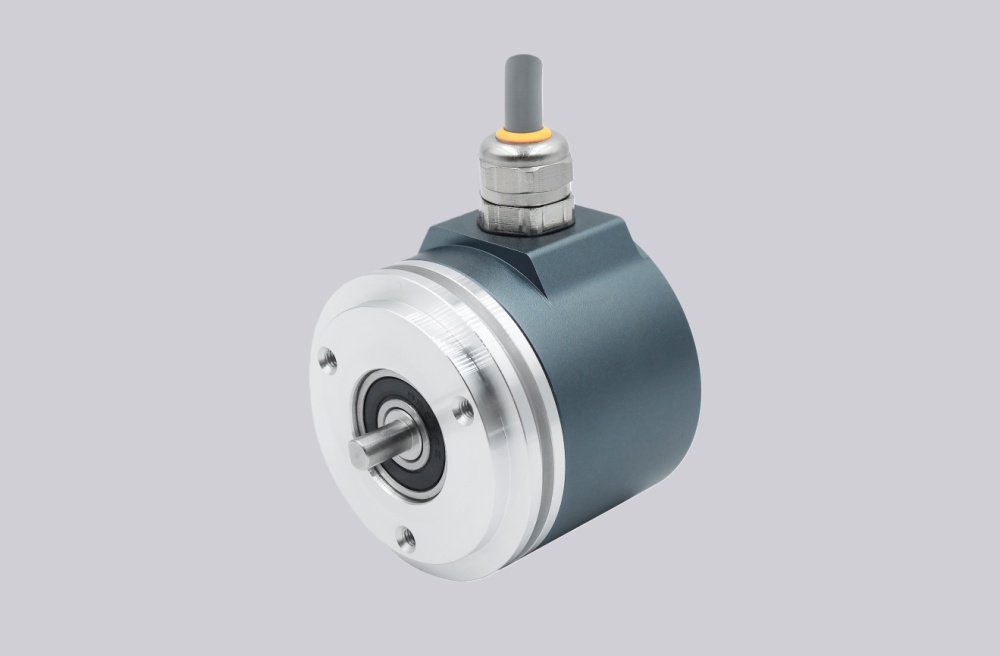
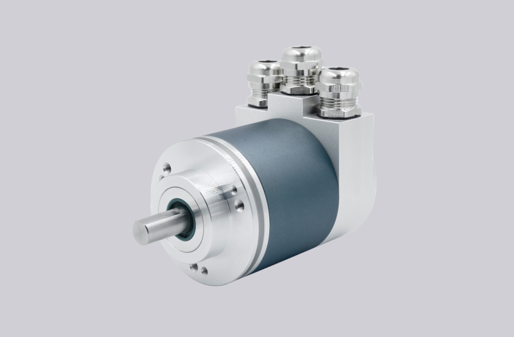
For 8.A124.M144.4412, EncoderWorks can provide a custom compatible replacement solution for large-shaft analog absolute feedback systems where the key checks are ø24 mm H7 bore fit, encoder-side locking-ring clamping, 70 mm torque-arm preload, 0–10 V analog scaling, and radial M12 wiring. This model should not be treated like an SSI or fieldbus AX encoder, because the controller reads position as an analog voltage signal rather than a clocked digital word or network telegram. Typical production lead time: 15 working days.
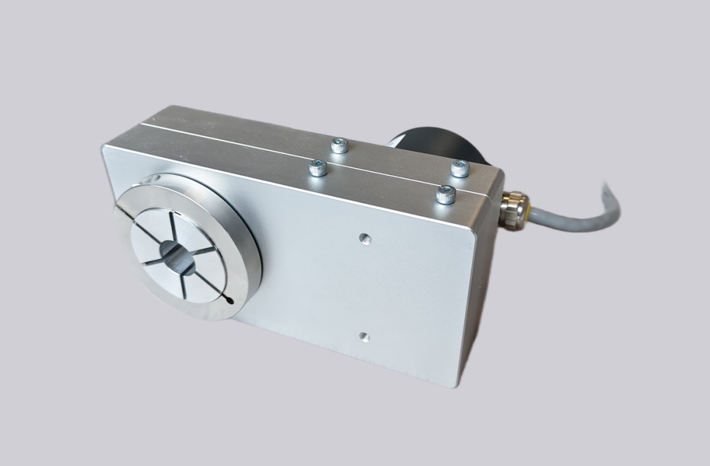
This configuration combines a Kübler AX hollow-shaft adapter with a Sendix M5861 analog absolute encoder. The AX section provides the ø24 mm hollow-shaft bore, locking ring on the encoder side, and 70 mm torque arm, while the encoder body provides 12-bit position conversion through a 0–10 V analog output. Replacement work should focus on shaft fit, clamp torque, torque-arm alignment, voltage scaling, supply range, analog input resolution, limit-switch function, M12 connector assignment, and shield grounding.
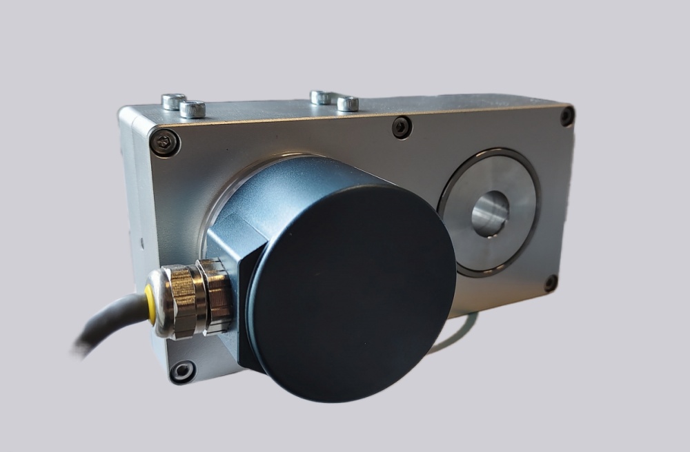
System Limits
The first system limit is analog scaling. The controller analog input must match the expected 0–10 V position range, zero point, span, direction, and filtering. If the voltage range is correct but the scaling table or analog input calibration is different, the machine can move to the wrong position without showing a communication fault.
The second limit is AX mechanical installation. The ø24 mm shaft must match the H7 adapter bore without forcing the clamp, and the locking ring must clamp from the encoder side. Shaft runout, excessive clamp force, or torque-arm preload can create housing movement, repeatability drift, or unstable analog feedback.
The third limit is the AX operating envelope. The adapter is rated IP64 and has temperature-dependent speed limits. High shaft speed, high ambient temperature, or a loaded torque arm can become the practical failure boundary before the analog output itself becomes unstable.
Wiring & Installation
Before replacement, record the M12 connector wiring for supply, ground, analog output, shield, and any limit-switch or expandable function used by the controller. Also record the analog input range, zero value, full-scale value, direction setting, filter time, and alarm thresholds from the PLC or drive.
During installation, confirm the ø24 mm H7 shaft fit, keep the locking ring on the encoder side, and align the 70 mm torque arm without preload. Route the analog signal cable away from inverter output wiring, maintain shield continuity through the M12 connector, and avoid ground loops between the encoder housing, machine frame, and cabinet earth. After startup, verify voltage at zero, voltage at full travel, direction trend, repeatability, limit-switch behavior, and torque-arm movement over several machine cycles.
Custom Compatible Solution
EncoderWorks can configure the replacement around the installed shaft and analog control system:
- Match the AX ø24 mm hollow-shaft adapter, encoder-side locking ring, 70 mm torque arm, and mounting envelope
- Preserve Sendix M5861 0–10 V analog position behavior, 12-bit scaling, direction, and limit-switch function
- Adapt the radial M12 connector layout, 15–30 VDC supply range, analog output wiring, and shield grounding
- Review clamp torque, shaft fit, torque-arm preload, IP64 installation limits, analog noise margin, and temperature-speed operating margin
Key Data
| Item | Data |
|---|---|
| Model | 8.A124.M144.4412 |
| Encoder type | Absolute encoder with AX hollow-shaft adapter |
| Encoder body | Sendix M5861 |
| Output type | Analog, 0–10 V |
| Resolution | 12 bit / 0–10 V |
| Supply voltage | 15–30 VDC |
| Bore | ø24 mm H7 hollow-shaft adapter |
| Locking ring position | Encoder side |
| Torque arm | 70 mm |
| Connection | 1× radial M12 connector |
| Adapter protection | IP64 |
| Adapter weight | Approx. 3.5 kg |
| Special function | Expandable, with limit-switch function |