


For CVS78E-022K5A0BI-0016, EncoderWorks can provide a custom compatible replacement focused on CANopen node identity, 16-bit singleturn mapping, and Ø12 mm Inox servo-shaft alignment. This model should not be treated as a multiturn encoder. The replacement risk is that the device may appear online, while the controller still receives the wrong singleturn angle because address, baud rate, termination, preset, direction, or coupling alignment was not reproduced.
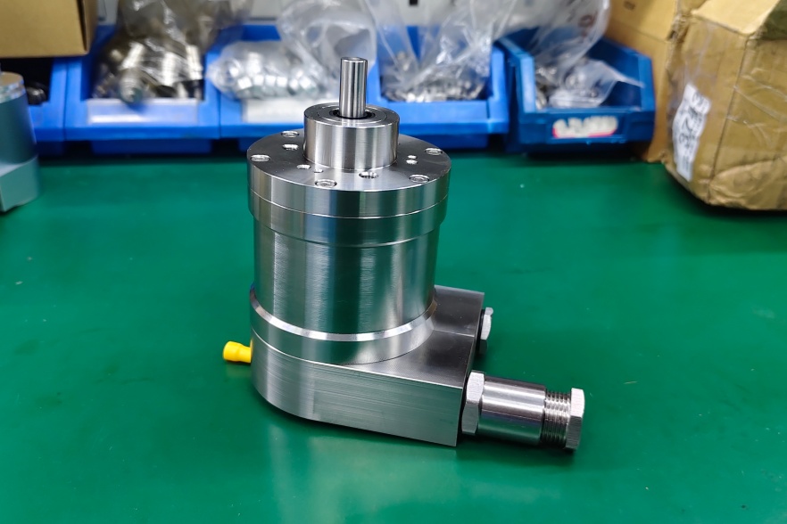
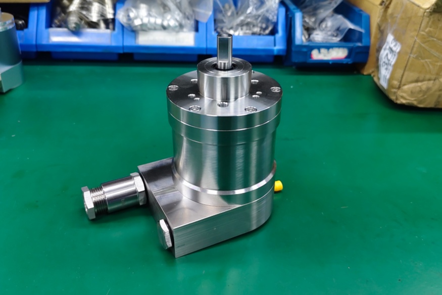
The CVS78E-022K5A0BI-0016 is a CANopen singleturn absolute encoder configuration with binary output code, 16-bit singleturn resolution, 10–30 VDC supply, explosion-proof IP66 construction, Inox housing execution, Ø12 mm solid shaft, servo flange, and K5 axial 5 m cable connection. The shaft is solid, not hollow, so the main mechanical check is coupling load rather than bore seating.
The first failure boundary is CANopen setup. Node address, baud rate, CAN high / CAN low wiring, CAN ground, and the 121 Ω termination state must match the original installation. If the node address is duplicated, the baud-rate switch is wrong, or termination is enabled at the wrong position, the encoder may power up but fail to deliver valid process data.
This replacement fails when the device is visible on the bus, but the PLC receives no valid or correct angle because CANopen address, baud rate, termination, CAN H/L wiring, or DS406 profile settings do not match the original encoder. That is a network-configuration failure, not a sensing failure.
The second boundary is singleturn parameter agreement. Resolution per revolution, preset value, counting direction, limit switches, cam switches, and operating mode can change the value delivered to the controller. A replacement can communicate normally and still report the wrong shaft angle if these parameters are not copied.
The replacement decision should first confirm explosion-proof requirement, Inox housing execution, Ø12 mm servo-flange geometry, K5 axial cable routing, CANopen DS301 / DS406 compatibility, 16-bit singleturn mapping, node address, baud rate, 121 Ω termination, CAN H/L wiring, preset value, counting direction, shield grounding, and coupling load. EncoderWorks treats CVS78E-022K5A0BI-0016 as an industrial encoder custom compatible solution where CANopen setup and Inox servo-shaft mechanics decide field reliability.
Typical production lead time: 15 working days.
Key Data
| Item | Data |
|---|---|
| Model | CVS78E-022K5A0BI-0016 |
| Encoder type | Singleturn absolute encoder |
| Interface | CANopen |
| Communication profile | DS301 |
| Device profile | DS406 / DS417 programmable class 2 |
| Resolution | 16-bit singleturn |
| Code | Binary |
| Supply voltage | 10–30 VDC |
| Housing execution | Inox |
| Shaft / flange | Ø12 mm solid shaft, servo flange |
| Connection | K5 axial cable, 5 m |
| Protection class | Explosion-proof, IP66 |
| Main engineering anchor | CANopen address and Inox servo shaft |
| Main failure boundary | Wrong node address, baud-rate mismatch, termination error, coupling preload |


