RVI58X-011K1R61N-01024 can be supported by EncoderWorks with a custom compatible replacement focused on ATEX cable mapping, 1024 PPR counter margin, and Ø10 mm clamping-flange alignment. This model should not be treated as a normal incremental encoder exchange. The real replacement risk is that the A/B/0 channels appear active, but the hazardous-area rating, inverted signal mapping, cable shielding, or flange coupling load does not match the original installation.
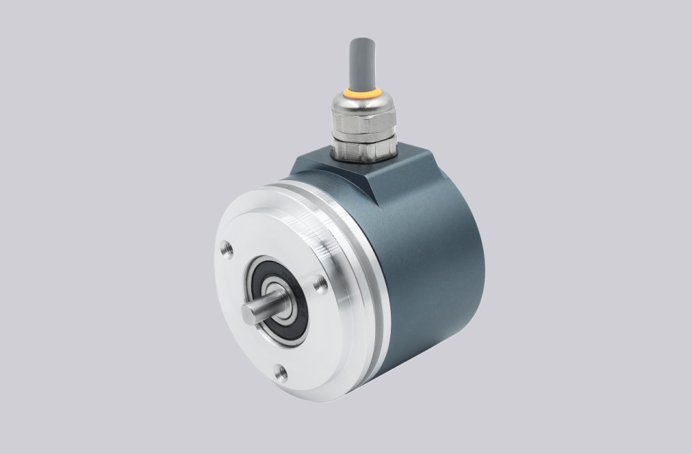
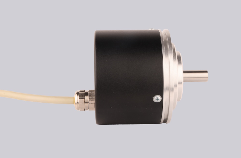
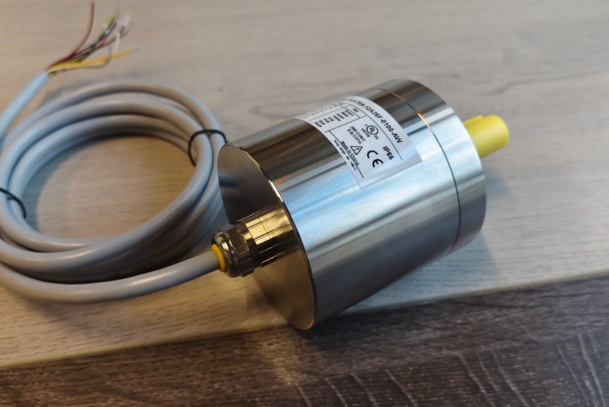
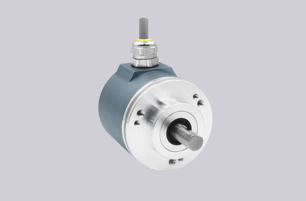
The RVI58X-011K1R61N-01024 is an ATEX incremental rotary encoder with Ø58 mm industrial housing, solid shaft, 011 Ø10 mm x 20 mm clamping flange, K1 cable output, radial exit direction, six-channel signal output, 10–30 VDC push-pull switching, and 1024 PPR resolution. The RVI58X platform is designed for Zone 2 and Zone 22 hazardous-area use, with ATEX approval, push-pull incremental output, and pulse counts up to 5000 PPR.
The first failure boundary is ATEX suitability. A replacement must preserve the hazardous-area design rather than only matching shaft size and pulse count. The datasheet lists ATEX marking for gas and dust areas, including II 3G Ex nA IIB T4 Gc X and II 3D Ex tc IIIC T105°C Dc X. If the site classification requires this rating, a non-ATEX encoder is not a valid substitute.

This replacement fails when the encoder counts correctly on the bench, but the installed machine no longer meets the required Zone 2 / Zone 22 boundary, cable sealing, or grounding practice. In that case, the failure is not pulse generation; it is unsafe replacement selection.
The second boundary is K1 cable mapping. RVI58X provides A, B, 0 and the inverted A, B, 0 channels. The cable conductors must be assigned by signal function: supply, ground, A/B/0, inverted channels, and shield. A wrong inverted channel can still produce motion feedback, but direction, reference, or counter noise rejection may be wrong at the controller.
At 1024 PPR, the 200 kHz output frequency ceiling normally gives useful headroom, but it should still be checked against actual shaft speed, cable length, input filtering, and counter threshold. Push-pull output does not compensate for poor shield termination or routing near inverter power cables.
Mechanically, the 011 clamping flange needs clean coupling alignment. The encoder shaft should not carry radial or axial load from a misaligned coupling. The RVI58X data lists axial 40 N and radial 60 N shaft-load limits, but these should be treated as boundaries, not normal installation preload.
The replacement decision should first confirm ATEX marking, 011 clamping-flange geometry, radial K1 cable routing, A/B/0 plus inverted channel mapping, 10–30 VDC push-pull compatibility, 1024 PPR counter margin, shield grounding, and coupling alignment. EncoderWorks treats RVI58X-011K1R61N-01024 as an industrial encoder custom compatible solution where hazardous-area compliance and six-channel signal integrity decide field reliability.
Typical production lead time: 15 working days.
Key Data
| Item | Data |
|---|---|
| Model | RVI58X-011K1R61N-01024 |
| Encoder type | ATEX incremental rotary encoder |
| Housing | Ø58 mm hazardous-area design |
| Shaft / flange | 011, Ø10 mm x 20 mm with clamping flange |
| Connection | K1 cable, radial exit |
| Signal output | A, B, 0 and inverted A, B, 0 |
| Output switching | 10–30 VDC push-pull |
| Pulse count | 1024 PPR |
| Output frequency | Max. 200 kHz |
| Application class | Zone 2 / Zone 22 hazardous areas |
| Main engineering anchor | ATEX cable mapping and clamping flange |
| Main failure boundary | Wrong ATEX selection, wrong channel mapping, shield fault, coupling preload |