For FSS58I-F1AADA3GN-0013, EncoderWorks can provide a custom compatible replacement focused on Inox housing protection, axial connector routing, 13-bit Gray code mapping, and Ø10 mm recessed hollow-shaft fit. This model should not be treated as only a smaller-bore version of the F3A encoder. The failure boundary moves to the small shaft interface, axial plug clearance, and whether the controller reads the same Gray-code position word after replacement.
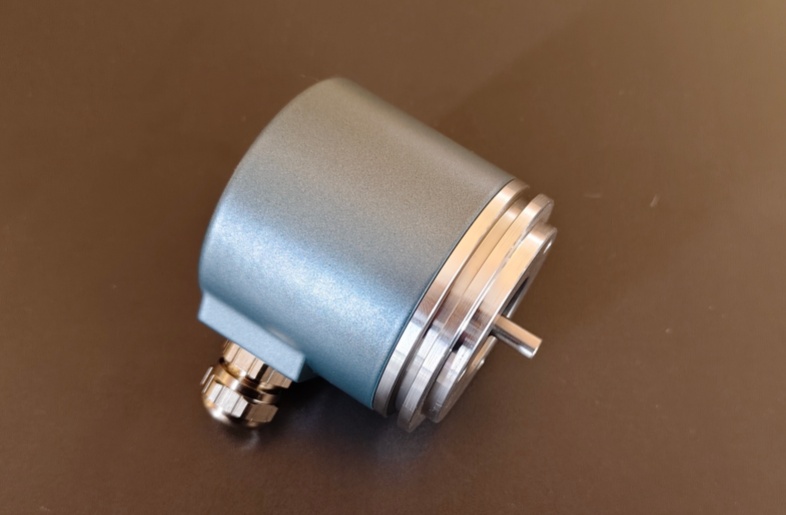
The FSS58I-F1AADA3GN-0013 is a singleturn absolute encoder with fast parallel push-pull output, 13-bit resolution, Gray code, Inox stainless-steel housing, F1A Ø10 mm recessed hollow shaft, AD 19-pin connector, axial exit direction, and V/R, LATCH, PRESET inputs. The FSS58 series uses direct code-disc readout for fast parallel data transfer and reaches a code change frequency up to 400 kHz.
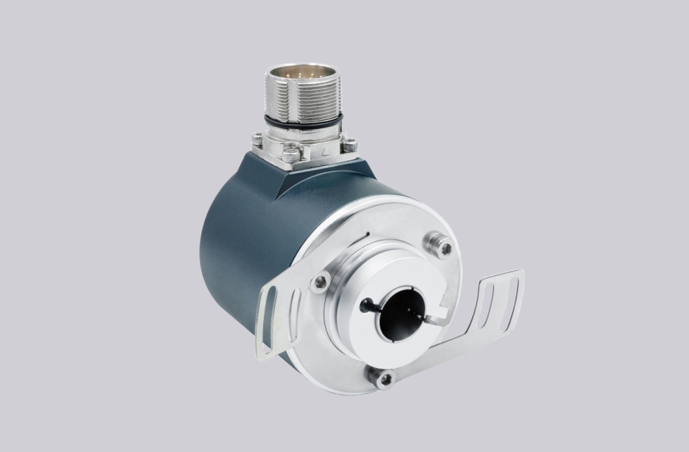

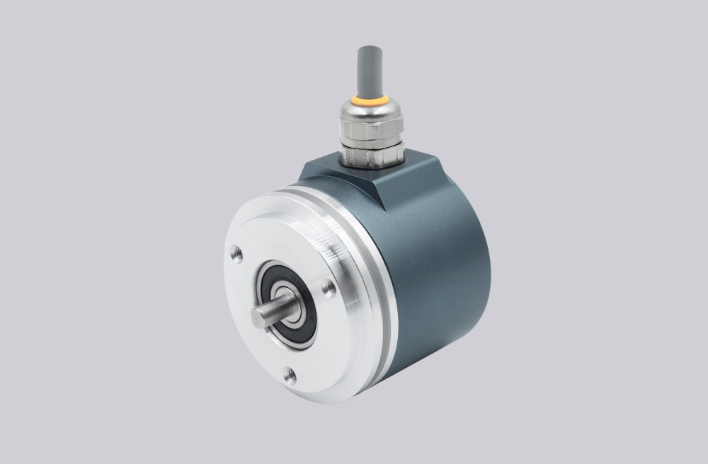
The first failure boundary is the Ø10 mm recessed hollow shaft. A small hollow-shaft interface has less tolerance for shaft burrs, eccentricity, angular error, or torque-rest preload. The encoder may fit by appearance, but if the torque rest pulls the housing into alignment, the shaft interface can carry stress that later appears as unstable position feedback.
This replacement fails when the Gray-code word is electrically active, but the machine position becomes unreliable because the Ø10 mm shaft fit or torque-rest geometry is mechanically loaded. That fault can look like a data problem even though the first failure is mechanical.
The second boundary is Gray code mapping. Gray code must be interpreted as Gray code by the controller, and Data bit 1 through Data bit 13 must match the original pin assignment. If the cabinet expects Gray but receives a shifted bit order, the output will still toggle normally while the decoded angle becomes wrong. This is especially risky when the replacement is wired by old cable color instead of connector function.
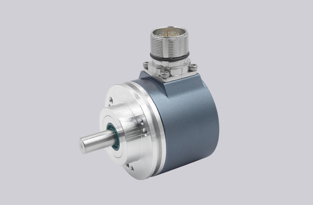
The axial AD connector also matters. Axial exit can improve cable routing in some machines, but it can create strain if the cable is bent sharply behind the encoder. The 19-pin connector carries data bits, power, V/R, LATCH, and PRESET, so plug orientation and cable clearance must be checked before commissioning.
LATCH and PRESET should be treated as control functions, not optional wires. LATCH freezes the parallel position word for stable reading, while PRESET electronically sets the output word to zero. A wrong PRESET input can create a false zero point, and an unused LATCH input can cause sampling errors near code transitions.
The replacement decision should first confirm Inox housing requirement, F1A Ø10 mm shaft fit, torque-rest freedom, axial AD connector clearance, 13-bit Gray code order, V/R direction logic, LATCH timing, PRESET behavior, supply voltage, and controller input thresholds. EncoderWorks treats FSS58I-F1AADA3GN-0013 as an industrial encoder custom compatible solution where small-bore shaft mechanics and Gray-code connector mapping must be verified together.
Typical production lead time: 15 working days.
Key Data
| Item | Data |
|---|---|
| Model | FSS58I-F1AADA3GN-0013 |
| Encoder type | Singleturn absolute encoder |
| Interface | Fast parallel push-pull |
| Housing | Ø58 mm Inox stainless-steel housing |
| Shaft type | Recessed hollow shaft |
| Shaft size | F1A, Ø10 mm x 30 mm |
| Connection | AD 19-pin connector |
| Exit direction | Axial |
| Output code | Gray code |
| Resolution | 13-bit singleturn / 8192 steps |
| Operating voltage | 10–30 VDC |
| Code change frequency | Up to 400 kHz |
| Inputs | V/R, LATCH, PRESET |
| Main engineering anchor | Inox axial Gray code and Ø10 shaft fit |
| Main failure boundary | Small-bore shaft stress, wrong Gray bit order, PRESET error |