For PVM58I-032AGR0BN-1213, EncoderWorks can provide a custom compatible replacement focused on Inox housing protection, Ø6 mm servo-flange centering, and PROFIBUS bus continuity. This model should not be handled like the Ø10 mm clamping-flange version. The smaller servo shaft and flange geometry make mechanical alignment more sensitive, while the PROFIBUS network still depends on the correct node address, termination state, Bus In/Bus Out wiring, and Class 2 parameter match.
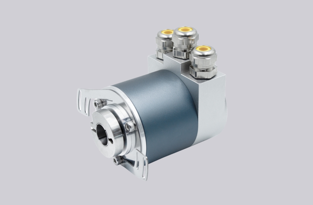
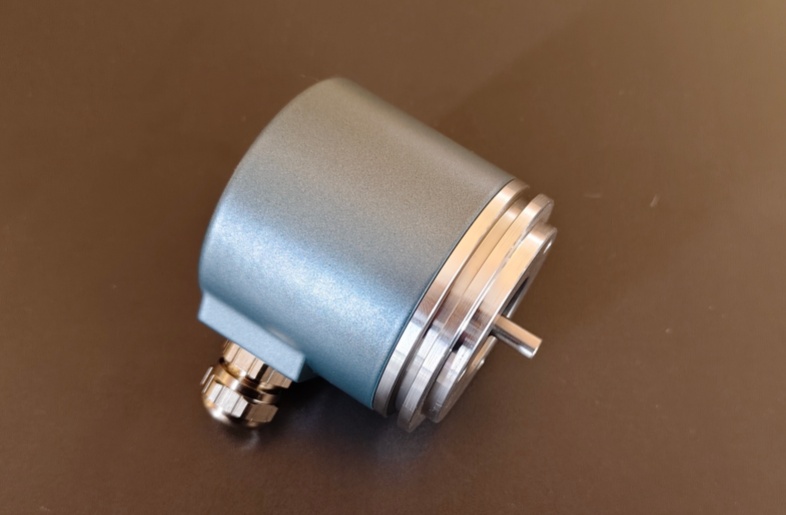
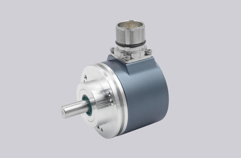
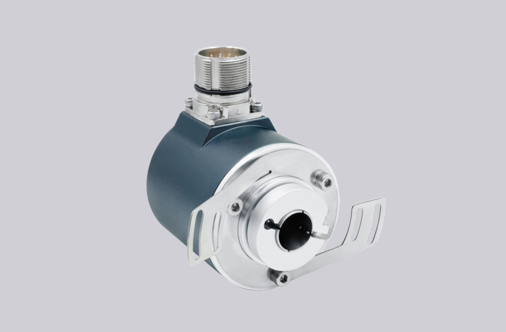
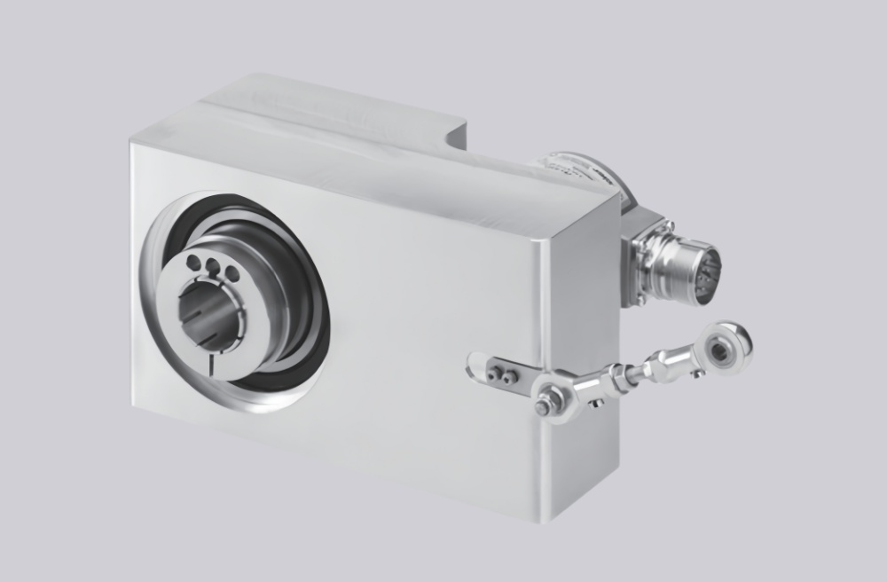
The PVM58I-032AGR0BN-1213 is a multiturn absolute rotary encoder with PROFIBUS interface, binary output code, Inox stainless-steel housing, AG removable terminal-compartment cover, and 032 shaft version, defined in the PVM58 type code as Ø6 mm x 10 mm with servo flange. The PVM58 platform supports PROFIBUS profile 3.062, Class 1 and Class 2 operation, programmable counting direction, scaling, preset, speed transfer, programmable limit switches, commissioning mode, and up to 30-bit overall resolution.
The first failure boundary is servo-flange centering. A Ø6 mm shaft cannot tolerate coupling misalignment, side load, or flange face error being absorbed by the encoder bearings. If the coupling is tightened before concentricity is checked, the encoder may communicate normally while the shaft carries radial stress. The PVM58 data gives defined shaft load limits, but those limits should be treated as boundaries, not as installation targets.
This replacement fails when the PROFIBUS master reaches Data Exchange, but the position value becomes unstable because servo-flange centering or coupling alignment is forcing load into the Ø6 mm shaft. That is a mechanical fault hidden behind normal bus communication.
The second boundary is PROFIBUS continuity. With the AG terminal cover, Bus In A/B and Bus Out A/B must remain correctly assigned. The supply only needs to be connected once, but the outgoing bus path still has to be preserved if the encoder is not the last participant. If Bus Out is broken, the fault may affect downstream devices rather than only this encoder.
Address and termination must be checked before changing parameters. The address is set by rotary switches from 1 to 99 and must be unique on the network. The 220 Ω termination resistor should be switched on only for the final participant. Wrong termination can create intermittent faults that appear after vibration, cable movement, or restart.
Class 2 parameter agreement is the third checkpoint. The 1213 resolution pattern still requires the correct scaling, preset, overall resolution, counting direction, and diagnostic behavior from the master. A replacement can be electrically healthy and still report the wrong absolute position if the project data is not copied.
The replacement decision should first confirm Inox housing requirement, 032 Ø6 mm servo-flange shaft fit, coupling alignment, flange centering, PROFIBUS address, Bus In/Bus Out polarity, termination switch state, GSD/profile compatibility, Class 2 scaling, preset value, counting direction, and LED diagnostic state. EncoderWorks treats PVM58I-032AGR0BN-1213 as an industrial encoder custom compatible solution where servo-flange mechanics and PROFIBUS bus continuity must be verified together.
Typical production lead time: 15 working days.
Key Data
| Item | Data |
|---|---|
| Model | PVM58I-032AGR0BN-1213 |
| Encoder type | Multiturn absolute rotary encoder |
| Interface | PROFIBUS, RS-485 |
| Housing | Ø58 mm industrial housing, Inox stainless steel |
| Shaft version | Solid shaft |
| Shaft / flange | 032, Ø6 mm x 10 mm with servo flange |
| Connection | AG removable housing cover with terminal compartment |
| Output code | Binary |
| Resolution class | 12-bit multiturn / 13-bit singleturn code pattern |
| Operating voltage | 10–30 VDC |
| Transfer rate | 0.0096–12 MBit/s |
| Main engineering anchor | Inox servo flange and PROFIBUS bus continuity |
| Main failure boundary | Servo-flange misalignment, broken Bus Out path, wrong termination, Class 2 mismatch |