

For 8.H120.4K5D.2048, EncoderWorks can provide a custom compatible replacement focused on 10–30 V push-pull receiver matching, 2048 PPR scaling, Ø17 mm 1:10 taper blind-shaft fit, and M23 clockwise connector wiring. This model should not be treated like a cylindrical blind-shaft or through-hollow-shaft version. The taper seat, center fastening, 150 mm torque arm, connector pinout, and A/B/0 inverted-channel mapping must match the original installation.
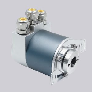
The 8.H120.4K5D.2048 is a heavy-duty optical incremental hollow-shaft encoder configuration with 2048 PPR, push-pull output with inverted signals, 10–30 VDC supply, Ø17 mm 1:10 taper blind hollow shaft, 150 mm torque arm, and radial M23 12-pin clockwise connector. The controller must keep the same quadrature mode, reference-pulse logic, and 2048 PPR scaling.
The first failure boundary is M23 signal mapping. A, B, 0 and inverted A/B/0 must be wired by function. If connector orientation, receiver threshold, shield bonding, inverted-channel assignment, or reference-pulse handling is wrong, the controller may see switching signals while still losing counts, reading the wrong direction, or missing the zero pulse.
This replacement fails when A/B/0 signals are present, but the controller loses counts or reads the wrong motion value because push-pull output behavior, 2048 PPR scaling, M23 pin mapping, inverted-channel assignment, or reference-pulse handling does not match the original encoder.
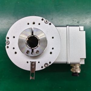
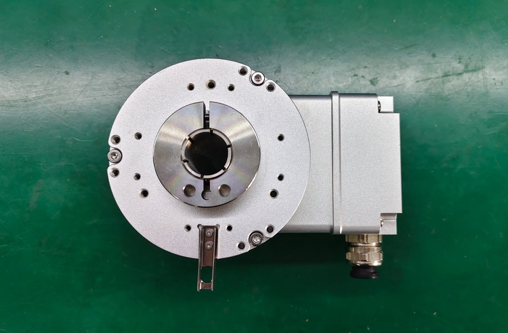
The second boundary is taper blind-shaft mechanics. The Ø17 mm 1:10 taper bore, center-fastening screw, insertion depth, 150 mm torque arm, radial load, axial load, IP67 sealing, and connector cable strain must be checked together. The taper connection should seat correctly without using the torque arm to compensate for misalignment.
The replacement decision should first confirm 2048 PPR scaling, 10–30 V push-pull receiver compatibility, A/B/0 plus inverted channel mapping, 300 kHz frequency margin, radial M23 clockwise connector assignment, Ø17 mm 1:10 taper blind-shaft fit, center-fastening requirement, 150 mm torque-arm geometry, IP67 sealing, shield grounding, cable routing, and shaft-load limits. EncoderWorks treats 8.H120.4K5D.2048 as an industrial encoder custom compatible solution where M23 wiring accuracy and taper-shaft mechanics decide field reliability.
Typical production lead time: 15 working days.
Key Data
| Item | Data |
|---|---|
| Model | 8.H120.4K5D.2048 |
| Encoder type | Heavy-duty incremental hollow-shaft encoder |
| Detection type | Optical |
| Pulse count | 2048 PPR |
| Output circuit | Push-pull with inverted signals |
| Signal output | A, B, 0 and inverted A, B, 0 |
| Supply voltage | 10–30 VDC |
| Max pulse frequency | 300 kHz |
| Shaft type | Taper blind hollow shaft |
| Shaft size | Ø17 mm, 1:10 taper |
| Mounting | 150 mm torque arm |
| Connection | Radial M23 12-pin connector, clockwise |
| Protection class | IP67 |
| Main engineering anchor | Push-pull output and taper blind shaft |
| Main failure boundary | Wrong M23 pin mapping, receiver mismatch, scaling error, taper-shaft preload |