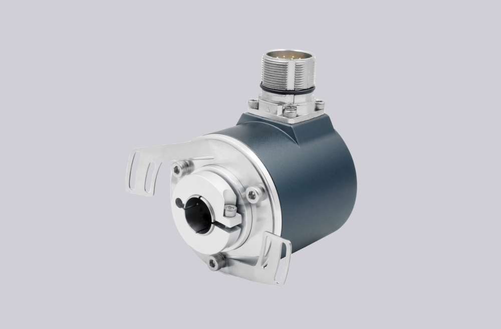
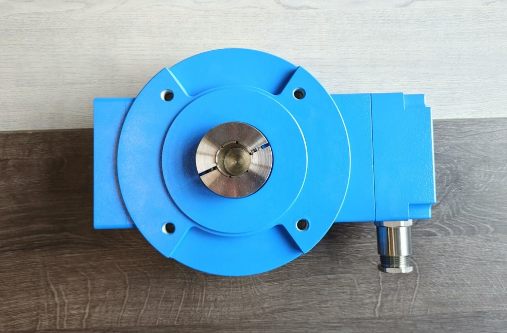
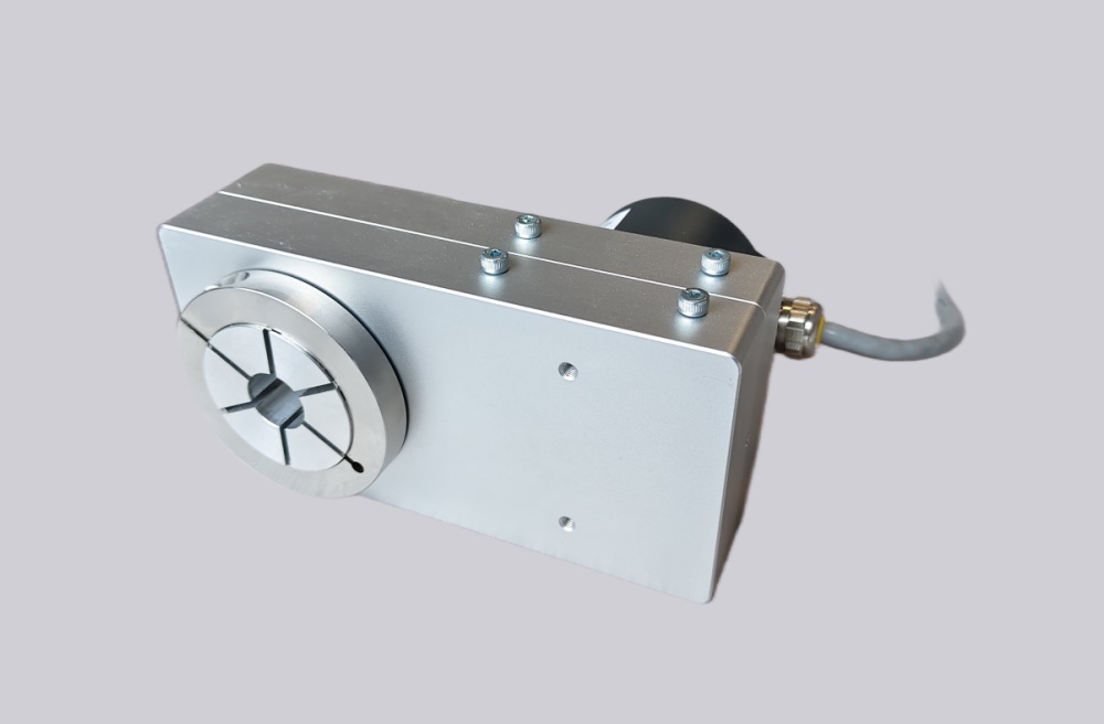
FG40KK-2500G-90G-NG should be replaced as a 2500 PPR dual-terminal-box incremental encoder, not as the previous 1024 PPR version with overspeed switching; EncoderWorks can configure a custom compatible replacement solution when the A/B 90° phase relationship, inverted channels, NG reference pulse, KK wiring layout, counter frequency margin, EMC grounding, and coupling alignment must remain unchanged. The main failure boundary is a counter system that receives pulses but loses phase stability, reference repeatability, or terminal-box separation. Typical production lead time: 15 working days.
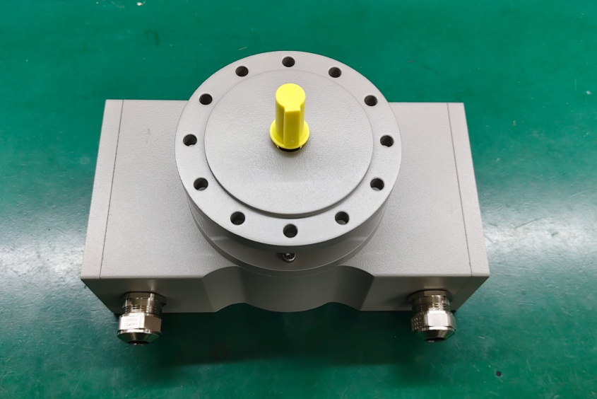
This configuration belongs to the FG 40 heavy-duty incremental encoder platform. It uses 2500 pulses per revolution with square-wave output, basic channel 0° A and pulse channel 90° B, inverted signals, and a mechanically defined NG reference pulse with inverted signal. The KK structure should be treated as a dual terminal-box or redundant-style wiring arrangement, not as a single-terminal-box K version. Replacement work should focus on pulse rate, A/B phase accuracy, N reference pulse position, output voltage level, counter input compatibility, shield termination, cable routing, and mechanical coupling preload.
System Limits
The first system limit is counter frequency. A 2500 PPR encoder generates more pulses per revolution than a 1024 PPR unit, so the controller input frequency, edge counting mode, maximum shaft speed, and noise margin must be checked. If the counter card has insufficient frequency margin, missed edges or false direction changes can occur at high speed.
The second limit is A/B/N signal integrity. The controller must receive A, /A, B, /B, N, and /N with the expected 90° phase displacement and reference-pulse behavior. If the inverted signals, phase displacement, or N pulse timing changes, the axis may count correctly during normal motion but fail during reference, zero, or direction checks.
The third limit is mechanical and EMC installation. Coupling misalignment, axial preload, radial load, weak shield bonding, or cable routing near inverter and motor wiring can degrade signal quality and shorten bearing life. The KK terminal-box layout must also be preserved if the machine uses separated signal routing or redundant wiring.
Wiring & Installation
Before replacement, record the terminal-box wiring for A, /A, B, /B, N, /N, supply voltage, GND, shield, and any diagnostic or error signal used by the machine. Confirm whether both terminal boxes are used for redundancy, separate cable routing, cabinet-side isolation, or signal distribution.
During installation, align the coupling without force and do not hammer the shaft or housing. Keep angular error, axial offset, and parallel displacement within the coupling tolerance used on the machine. Route signal and supply wiring away from inverter, motor, brake, contactor, and solenoid cables. Use low-impedance grounding, maintain shield continuity, and seal the terminal boxes and cable glands before startup. After commissioning, verify pulse count, direction, N reference repeatability, counter frequency margin, terminal-box wiring separation, and signal stability at operating speed.
Custom Compatible Solution
EncoderWorks can configure the replacement around the installed drive and counter system:
- Match 2500 PPR square-wave incremental output with A/B 90° phase relationship and inverted channels
- Preserve NG reference pulse behavior, KK dual terminal-box layout, supply voltage, output level, and counter input compatibility
- Adapt the FG 40 mechanical envelope, flange or foot mounting requirement, shaft interface, coupling alignment, and cable-gland layout
- Review counter frequency margin, shield grounding, EMC routing, terminal separation, bearing load, and reference-pulse repeatability
Key Data
| Item | Data |
|---|---|
| Model | FG40KK-2500G-90G-NG |
| Encoder type | Heavy-duty incremental encoder |
| Series | FG 40 |
| Connection structure | KK dual terminal box / redundant-style version |
| Pulses per revolution | 2500 PPR |
| Signal output | Square wave A/B, 90° phase |
| Inverted signals | Yes |
| Reference pulse | NG, with inverted signal |
| Supply voltage | 12–30 VDC |
| Output type | Push-pull line driver |
| Max frequency | 200 kHz |
| Standard shaft | 11j6 × 30 mm |
| Optional shaft | 14j6 × 30 mm |
| Key checks | Counter frequency, A/B phase, N pulse, terminal-box wiring, EMC grounding |