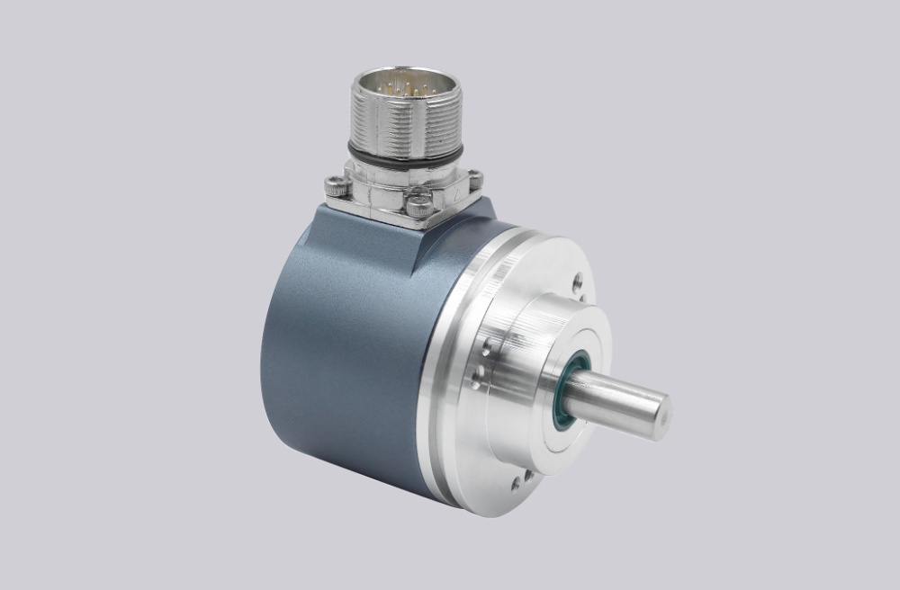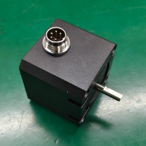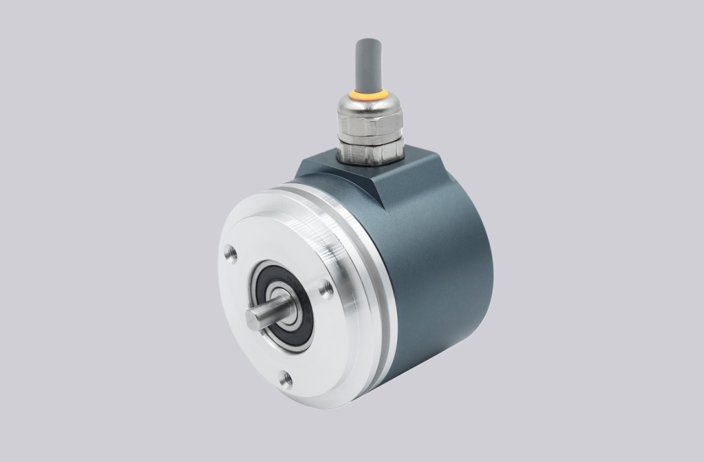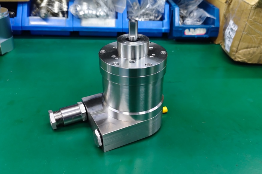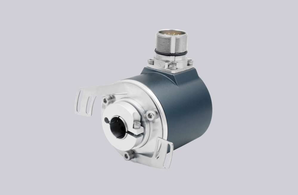



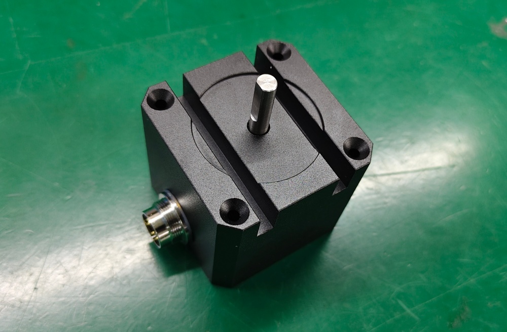
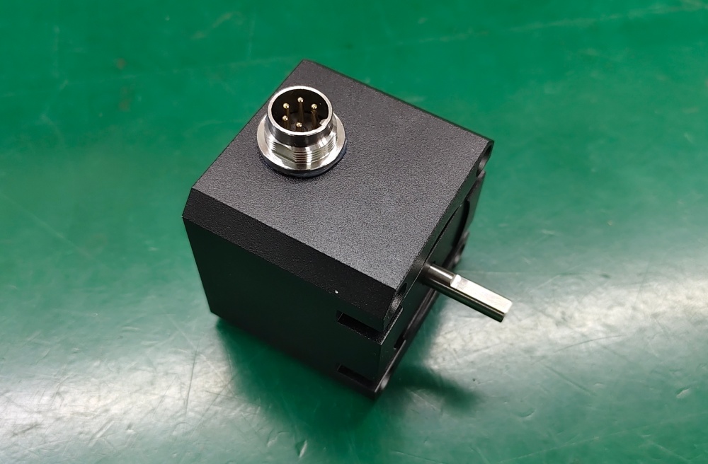
When replacing 20-2951-1024, EncoderWorks can configure a custom compatible replacement solution around the 1024 PPR incremental scaling, 10–30 VDC push-pull output, M16 5-pin A/B/0 signal mapping, Ø6 mm shaft fit, rectangular housing alignment, and IP40 installation boundary. The main failure boundary is a compact rotary feedback system that may produce pulses but still cause wrong speed scaling, direction reversal, reference loss, connector mismatch, shaft-load stress, or intermittent counting if the PPR value, output type, pin assignment, or mounting geometry is changed. Typical production lead time: 15 working days.
This model belongs to the 20-295 rectangular incremental rotary encoder platform. The “1” in 20-2951 identifies the 10–30 VDC push-pull output version, while 1024 is a listed pulse count for this series. Because 1024 PPR is often used for controller scaling and speed feedback, replacement work should focus on preserving the A/B phase relationship, the 0 reference signal, the 5-pin connector assignment, and the mechanical limits of the Ø6 mm shaft.
System Limits
The first limit is 1024 PPR scaling and A/B/0 signal behavior. The controller input, edge-counting mode, direction logic, and reference-signal requirement must match the installed configuration. If 1024 PPR is replaced by 1000, 1200, 2048, or another count, or if the 0 reference signal is ignored or mapped to the wrong input, the machine may show wrong speed, failed referencing, direction error, or unstable counting.
The second limit is M16 connector mapping and rectangular-shaft installation. The 5-pin connector must preserve GND, +Ub, A, B, and 0 assignment, while the Ø6 mm shaft, square mounting face, radial connector clearance, 3000 rpm speed limit, 10 N axial/radial shaft-load boundary, and IP40 protection class must remain compatible with the machine. Wrong pinout, cable strain, excessive coupling load, poor centering, or use beyond the IP40 sealing boundary can cause signal dropouts, bearing stress, or early mechanical failure.
Wiring & Installation
Before replacement, verify the installed pulse count, output switching code, connector orientation, controller input type, and whether the machine uses the 0 reference signal. The 10–30 VDC push-pull version should not be replaced with a 5 V RS422 version unless the controller input and wiring are changed accordingly.
During installation, align the Ø6 mm shaft coupling without forcing the shaft, keep axial and radial loads within the original boundary, and check that the rectangular housing can be fixed without twisting the shaft. Route the cable so that the radial M16 connector is not pulled sideways, and keep feedback wiring away from motor, inverter, brake, and contactor cables.
Custom Compatible Solution
EncoderWorks can configure the replacement around the installed rectangular incremental encoder interface:
- Match 1024 PPR scaling, 10–30 VDC push-pull output, and controller input level
- Preserve A/B phase behavior, 0 reference-signal use, and M16 5-pin connector mapping
- Adapt the rectangular housing fit, square mounting face, radial connector orientation, and Ø6 mm shaft interface
- Review 160 kHz frequency margin, coupling load, IP40 installation boundary, cable routing, and reference-pulse repeatability before shipment
Key Data
| Item | Data |
|---|---|
| Model | 20-2951-1024 |
| Encoder type | Incremental rotary encoder |
| Housing style | Rectangular / cuboid housing |
| Output switching | Code 1, 10–30 VDC push-pull |
| Pulse count | 1024 PPR |
| Signal channels | A, B, and 0 reference signal |
| Output frequency | Max. 160 kHz |
| Connector | 9414 M16, 5-pin |
| Pin mapping | GND 1, +Ub 2, A 3, B 4, 0 5 |
| Shaft | Ø6 mm solid shaft |
| Rotational speed | Max. 3000 rpm |
| Shaft load | 10 N axial, 10 N radial |
| Protection class | IP40 |
| Key replacement checks | 1024 PPR scaling, push-pull output, A/B/0 mapping, M16 pinout, Ø6 shaft alignment, IP40 boundary |