EncoderWorks develops a concise custom compatible solution for FGH4K-1200G-90G-NG/20P, focused on preserving 1200 PPR incremental feedback while matching the 20P hollow-shaft mounting and terminal-box grounding behavior. The replacement fails when the pulse count is correct, but the machine grounding, cable shield path, A/B phase order, or NG reference pulse is not restored with the same low-resistance EMC boundary. Typical production lead time: 15 working days.
Where the System Fails First
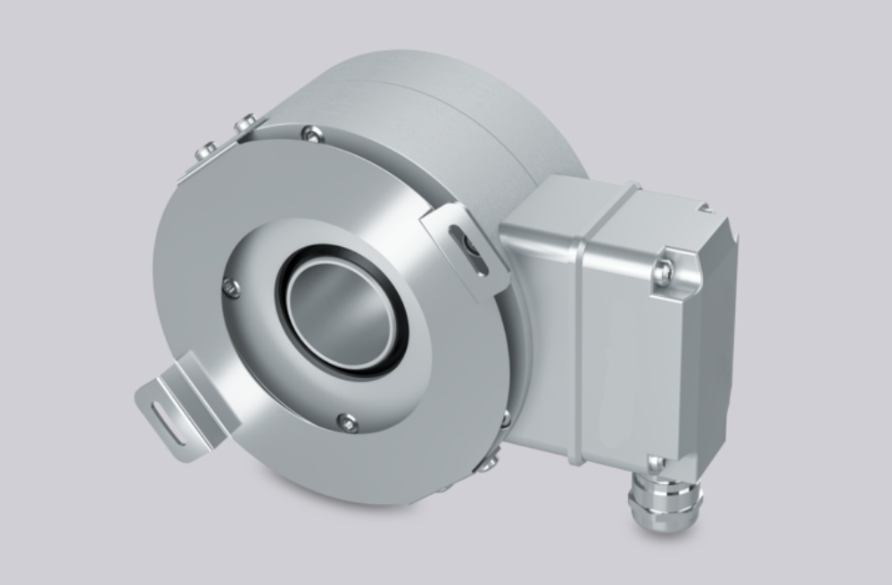
The controller reads FGH4K-1200G-90G-NG/20P as an incremental hollow-shaft encoder with A/B square-wave channels shifted by 90° and an NG reference pulse with inverted signal. The FGH 40 manual lists 1200 PPR as a standard pulse rate. The square-wave output uses a push-pull line driver, with 12–30 VDC supply and a listed maximum frequency of 200 kHz unless otherwise specified.
This replacement fails when the encoder is electrically compatible but the grounding path is weak. At 1200 PPR, the counter may have enough frequency margin, yet the signal can still become unstable if the shield is not bonded properly or the cable is routed near high-energy equipment.
A stable replacement must first reproduce the original 1200 PPR count, A/B phase order, NG reference behavior, and low-resistance shield grounding before the encoder can be judged compatible.
Hollow-Shaft and EMC Boundary
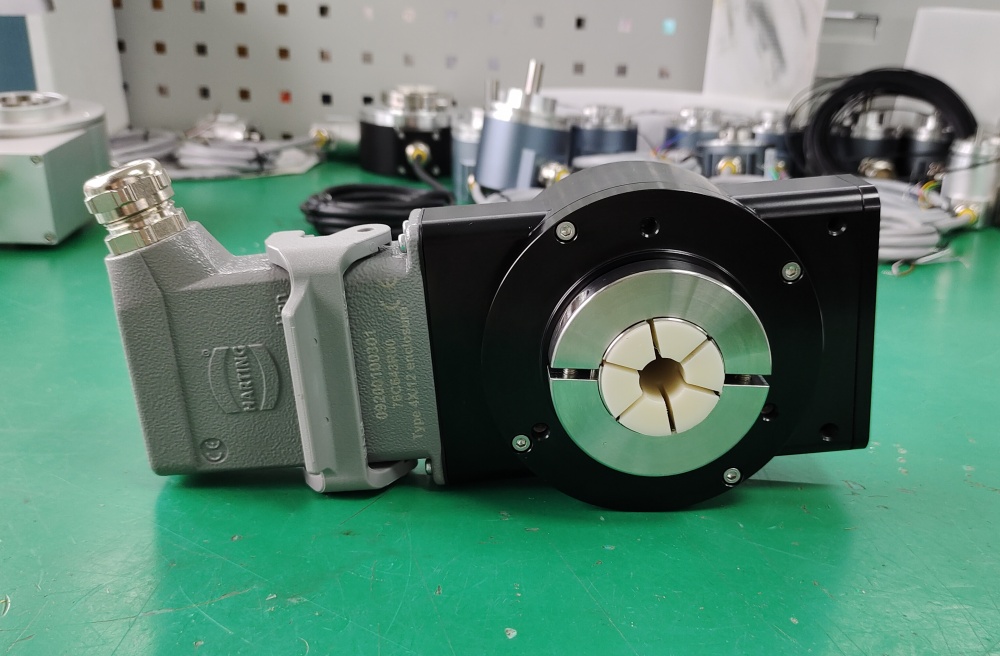
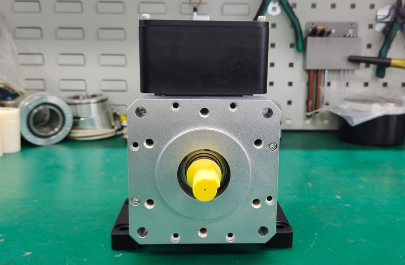
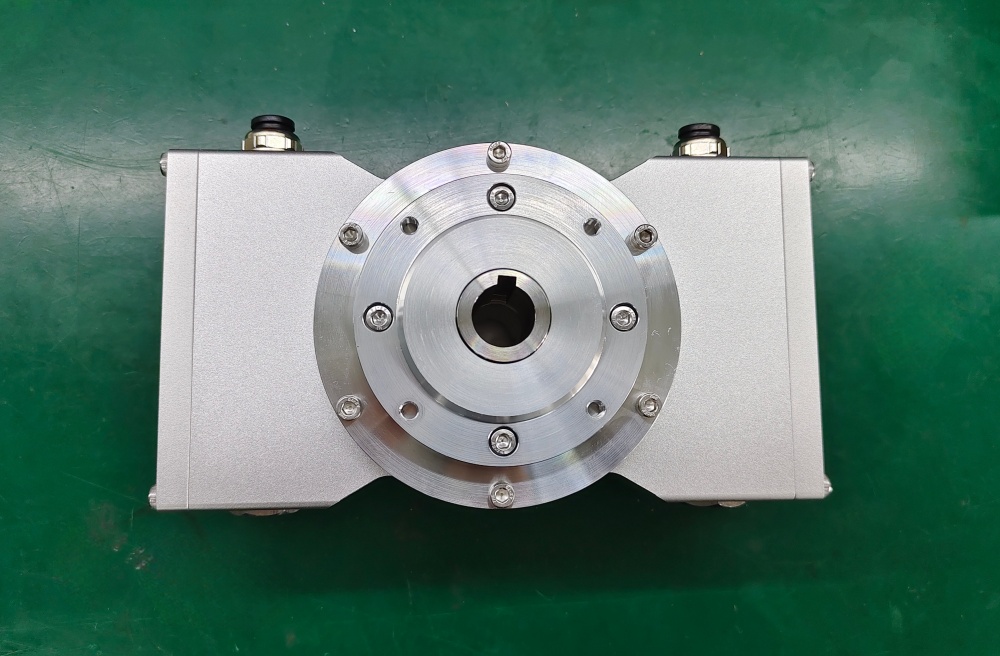
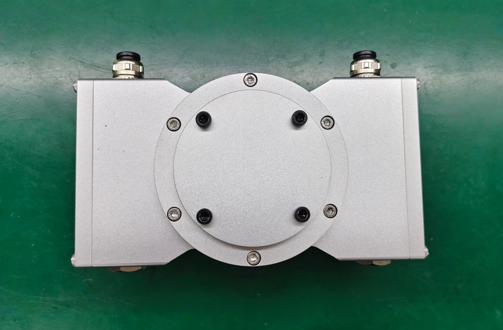
The /20P code indicates a 20 mm hollow shaft with feather key. The manual warns against hammer impact during installation, requires careful adapter-shaft alignment, and gives 0.05 mm as the maximum radial runout of the adapter shaft. It also states that the torque link must rotate freely around the link rod heads; otherwise bearing damage may occur.
For FGH4K-1200G-90G-NG/20P, the unique checkpoint is not extreme counter frequency. It is standard pulse feedback with correct grounding discipline. The manual recommends shielded cables, low-resistance machine grounding, cable routing away from inverters and motors, and a grounding strap connected to a nearby bare-metal grounding point. If this boundary is ignored, the fault may appear as intermittent speed feedback rather than a clear encoder failure.
Installation Notes
- Set the controller counter value before startup
- Check A/B phase order against machine rotation
- Test the NG reference pulse during slow rotation
- Mount the hollow shaft without hammer impact
- Keep the torque bracket free from preload
- Keep shield bonding short, continuous, and low-resistance
- Tighten terminal-box entries and cable glands before operation
- Route signal wiring away from inverter, motor, brake, and contactor cables
Key Data
- Model: FGH4K-1200G-90G-NG/20P
- Type: Incremental hollow-shaft encoder
- Pulse rate: 1200 PPR
- Signal format: G, 90° A/B square-wave
- Reference pulse: NG, with inverted signal
- Supply voltage: 12–30 VDC
- Output: Push-pull line driver
- Max frequency: 200 kHz
- Hollow shaft: 20P
- Protection: IP65 standard
- Standard temperature: 0°C to +70°C
- Main replacement focus: grounding discipline, 1200 PPR scaling, NG reference pulse, hollow-shaft alignment