




For OCD-PPA1G-00AA-B110-2RW, EncoderWorks can provide a custom compatible replacement solution for 9-bit parallel absolute feedback systems where the critical checks are bit-line mapping, latch timing, DIR logic, and ø11 mm blind-hollow shaft fit. A replacement may power on and output signals, but still fail if the controller samples unstable Gray-code states, reads a swapped bit line, or receives the opposite counting direction. Typical production lead time: 15 working days.
This encoder type is normally used with PLC input cards, counter modules, or legacy controllers that read absolute angular position through parallel digital inputs instead of SSI, CANopen, or Profibus. During replacement, the electrical interface and the mechanical mounting must be verified together. The push-pull output level, 9-bit Gray-code interpretation, latch input, direction control, cable color assignment, radial cable routing, and blind-hollow shaft engagement all affect whether the replacement can operate without control program changes.
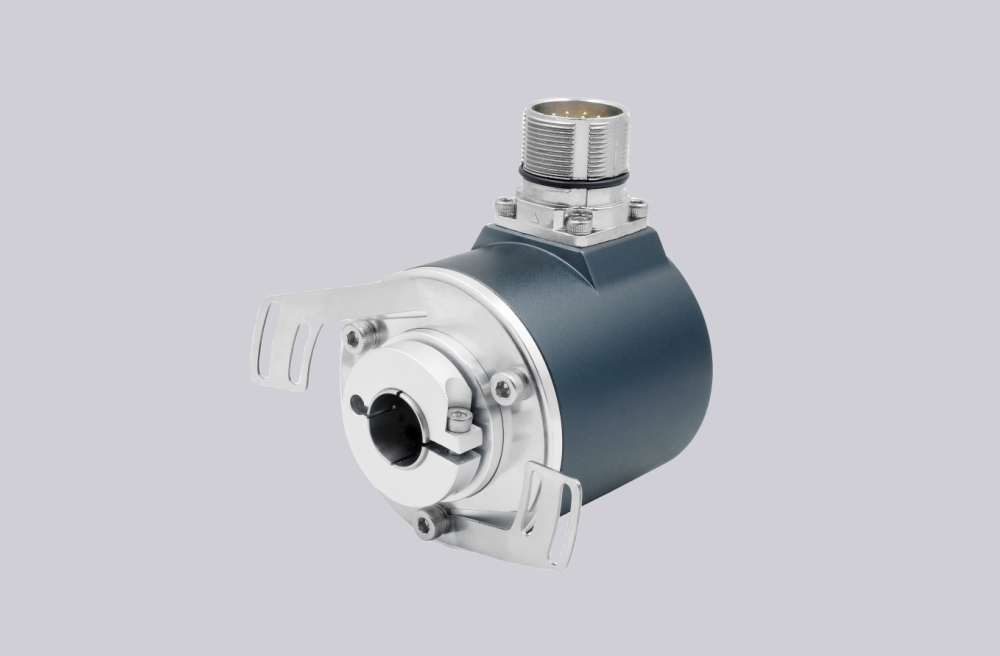
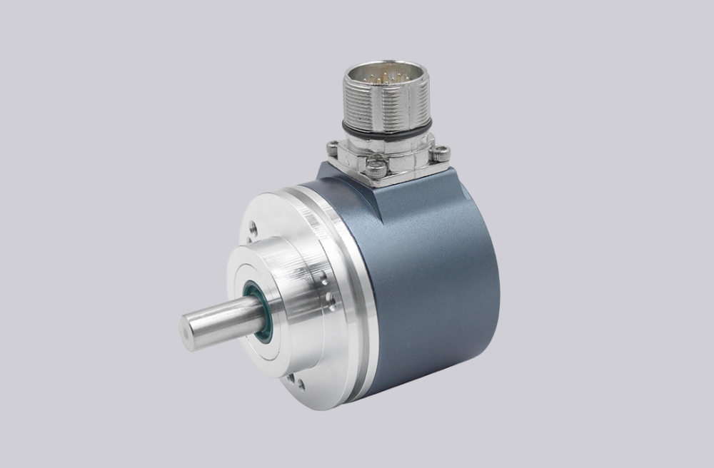
System Limits
The first system limit is 9-bit parallel signal integrity. OCD-PPA1G-00AA-B110-2RW transmits the singleturn position value through individual bit lines. Each bit must be connected to the correct controller input and must remain stable under machine noise. A swapped high-order bit can create a large position error, while an unstable low-order bit may appear as repeated indexing error or small position drift. Because the output uses Gray code, the controller must interpret the value as Gray code rather than straight binary.
The second limit is latch timing. Parallel encoder lines do not always reach the PLC input image at the same instant, especially when the shaft is moving through a transition point. If the controller samples during a state change, it may capture a false intermediate value. The latch line should therefore be checked against the controller scan cycle and the actual moment when position data is read.
Direction logic is another common failure boundary. The counting direction is set through the cable or connector. If the DIR line is wired differently from the previous encoder, the machine may show a valid absolute position but move in the wrong value trend during rotation. This should be verified from the controller display during slow shaft movement, not only by checking output voltage.
EMC must also be reviewed because parallel feedback uses multiple conductors. Long cable routing near inverter outputs, motor power, brake coils, or solenoid wiring can inject noise into individual bit lines. Shield grounding, cable separation, and input filtering are important for stable position reading.
The mechanical limit is the blind-hollow shaft interface. The ø11 mm blind hollow shaft, 30 mm shaft depth, and ø58 mm flange must be installed without radial preload or excessive dynamic misalignment. If the shaft is forced during installation, bearing load and vibration can reduce service life even when the electrical output remains normal.
Wiring & Installation
Before removing the existing encoder, record the cable assignment for Bit 1 through Bit 9, Latch, DIR, supply, and GND. The replacement should be wired channel by channel rather than by assumed color sequence. Confirm that the controller input stage accepts push-pull output at 10–30 VDC and that the software expects Gray-code position data.
After wiring, rotate the shaft slowly through the working range and confirm that the position value changes smoothly in the expected direction. Then test latch behavior under the real machine scan condition. If the application uses electronic cam windows, indexing stops, or position-based interlocks, check those switching points again after zero alignment.
Custom Compatible Solution
EncoderWorks can configure the replacement around the original machine requirements:
- Match 9-bit parallel output behavior, push-pull voltage level, Gray-code reading, and controller input mapping
- Adapt the ø58 mm blind-hollow flange, ø11 mm bore, 30 mm shaft depth, radial cable exit, and 2 m cable length
- Verify latch, DIR, cable color mapping, position direction, and controller-side value trend before shipment
- Review shielding, grounding, cable routing, and blind-hollow shaft load limits for stable replacement operation
Key Data
| Item | Data |
|---|---|
| Model | OCD-PPA1G-00AA-B110-2RW |
| Encoder type | Absolute singleturn encoder |
| Interface | Bit Parallel |
| Output driver | Push-Pull |
| Supply voltage | 10–30 VDC |
| Current consumption | ≤400 mA at 10 VDC, ≤180 mA at 24 VDC |
| Power consumption | ≤1.5 W |
| Start-up time | <1 s |
| Settling time | 80 ms |
| Sensor technology | Optical |
| Resolution | 9 bit singleturn |
| Code | Gray |
| Default sense signal | Clockwise shaft movement, front view on shaft |
| Protection class | IP65 shaft / IP65 housing |
| Operating temperature | -30 °C fixed, -5 °C flexible, up to +70 °C |
| Housing material | Steel |
| Flange type | Blind Hollow, ø58 mm |
| Shaft type | Blind Hollow, depth 30 mm |
| Shaft diameter | ø11 mm |
| Shaft material | Stainless steel V2A / 303 |
| Max mechanical speed | ≤12000 rpm |
| Max static misalignment | Axial ±0.3 mm, radial ±0.5 mm |
| Max dynamic misalignment | Axial ±0.1 mm, radial ±0.2 mm |
| Vibration resistance | ≤10 g, 10 Hz–1000 Hz |
| Shock resistance | ≤100 g, half sine 6 ms |
| Connection orientation | Radial |
| Cable length | 2 m |
| Cable type | PVC, 9.3 mm diameter |
| Approval | CE |







