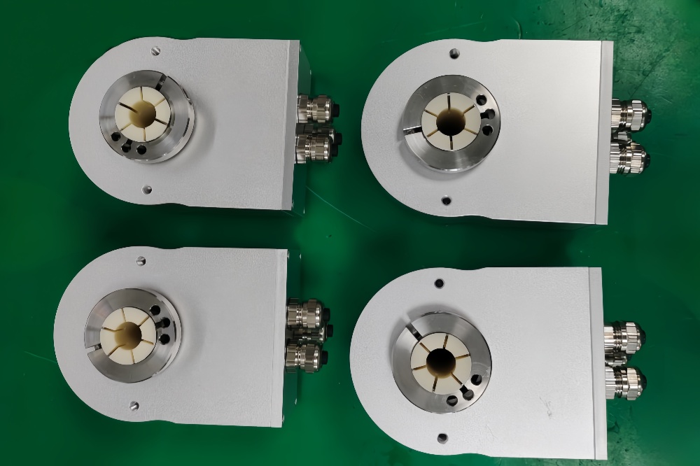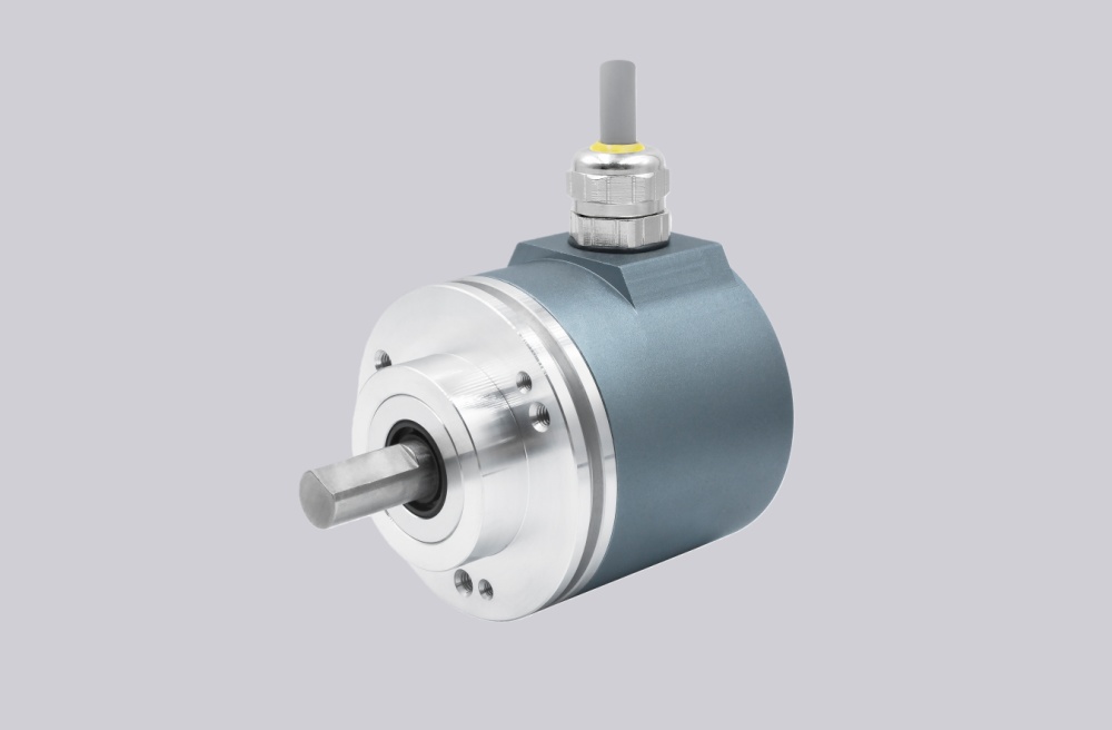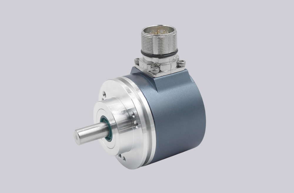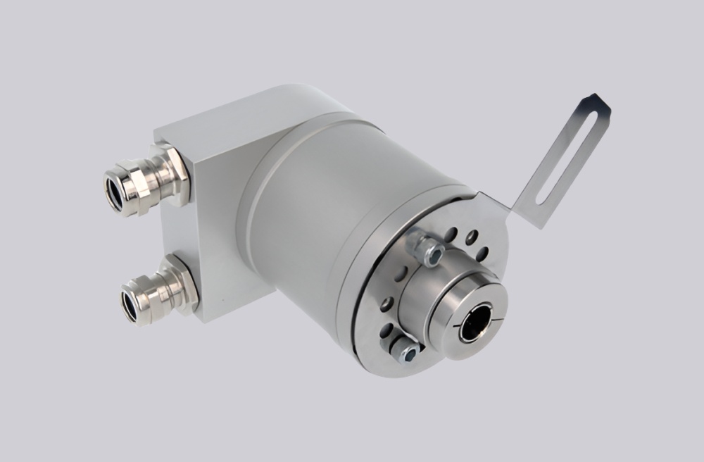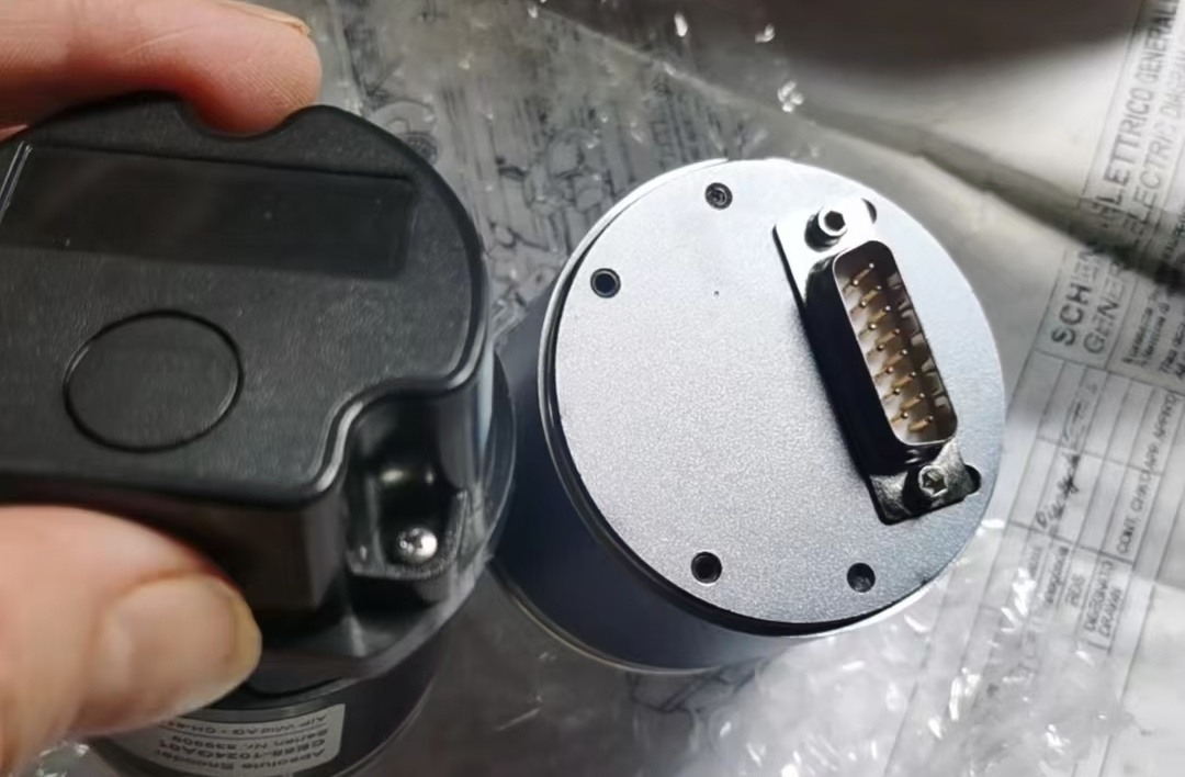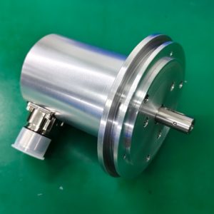



We provide a custom compatible solution for the CEV65M-10863 encoder, built for systems where 1500-step / 35-turn absolute feedback must stay stable through parallel push-pull wiring, SUB-D 37-pin mapping, latch timing, DataBus control, preset logic, and Gray-code decoding.
Model reading from the document:
- CEV65M-10863 = absolute rotary encoder
- 1500 steps per revolution
- 35 revolutions
- Parallel push-pull interface
- Gray code
- 11–27 VDC supply
- 11–27 V output level
- ZB80 flange
- 12FL / 24 shaft
- SUB-D 37-pin connector
- 0.5 m radial cable
- IP65 protection
- -20 °C to +70 °C temperature range
Typical production lead time: 15 working days.
This model is not a bus encoder and not an SSI encoder. The first weak point is usually parallel bit mapping, latch timing, DataBus tristate control, preset wiring, or direction input logic. If any of these are wrong, the controller may read a complete position word, but the value will be unstable or simply wrong.
Where the System Fails First
The pinout defines O_D0 to O_D23 as data outputs. That means the controller must read a wide parallel word correctly, not just one serial data line. Parallel feedback fails differently from SSI or Profibus: the signal may not disappear completely; instead, one bit shifts, one input floats, or the latch timing captures a transition state.
Typical failure points:
- Wrong O_D0–O_D23 mapping → corrupted Gray-code position
- Latch timing error → unstable sampled value
- DataBus_IN misuse → outputs forced into tristate
- Wrong Direction input → reversed position logic
- Preset1 / Preset2 wiring error → false reference position
- Poor SUB-D shielding → bit-level noise under EMC load
The document also lists BUS, F/R, LATCH, Preset 1+2, and programmable options. These are the real integration points. For this model, the weakest layer is not the encoder disk; it is the PLC input structure and whether the SUB-D wiring preserves every bit cleanly.
Mechanical and Wiring Boundary
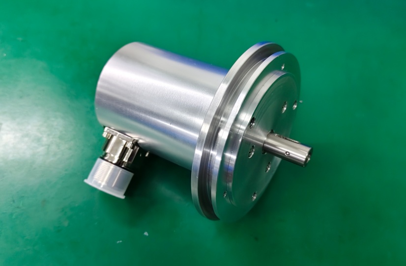
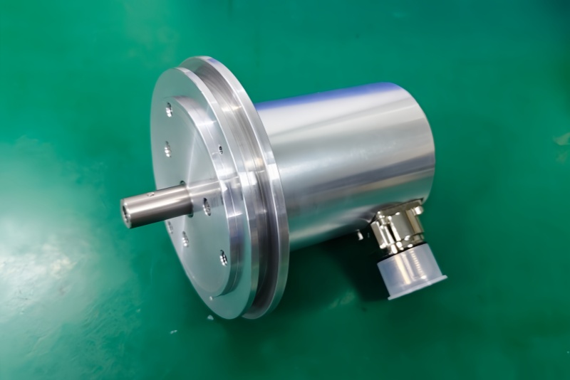
The drawing shows a larger ZB80 flange, 12 mm flat shaft / 24 mm length, 0.5 m cable, and 37-pin SUB-D connector. Mechanically, the larger flange and shaft help installation rigidity, but the cable and connector still decide signal reliability. A loose SUB-D shell, weak shield, or strained cable can create random bit errors that look like encoder failure.
The 0.5 m cable reduces long-cable risk, but it does not remove cabinet-side EMC problems. Keep the SUB-D connection away from inverter wiring, relay coils, and motor power routing. Parallel push-pull outputs are direct and fast, but they are also unforgiving when grounding and input reference are poor.
Installation Notes
- Keep the model format as CEV65M-10863
- Map O_D0 to O_D23 exactly at the controller input
- Verify Gray-code decoding before commissioning
- Check Latch timing before judging position instability
- Do not activate DataBus_IN unless tristate behavior is intended
- Confirm Direction, Preset1, and Preset2 logic before startup
- Keep SUB-D shielding and cable strain relief solid
- De-energize the system before wiring or connector work
Key Data
- Model: CEV65M-10863
- Type: Absolute rotary encoder
- Interface: Parallel push-pull
- Code: Gray
- Resolution: 1500 steps / revolution
- Multiturn range: 35 revolutions
- Supply voltage: 11–27 VDC
- Output level: 11–27 VDC
- Flange: ZB80
- Shaft: 12FL / 24
- Connector: SUB-D 37-pin
- Cable length: 0.5 m
- Connector position: PG radial
- Protection: IP65
- Temperature range: -20 °C to +70 °C
- Options: BUS, F/R, Latch, Preset 1+2, Programmable
- Pinout: ST168B
- Parameter file: CEV65M-10863
- Firmware: 43770D